
Loudspeaker low profile quarter wavelength transmission line and enclosure and method

a technology of transmission line and loudspeaker, which is applied in the field of loudspeaker systems, can solve the problems of affecting the performance of volume relative to the port volume, affecting the entire listening area, and unable to achieve the desired frequency of sound waves, so as to reduce the turbulence of air flow

Inactive Publication Date: 2007-10-23
EARTHQUAKE SOUND
View PDF10 Cites 31 Cited by
  • Summary
  • Abstract
  • Description
  • Claims
  • Application Information

AI Technical Summary

Benefits of technology

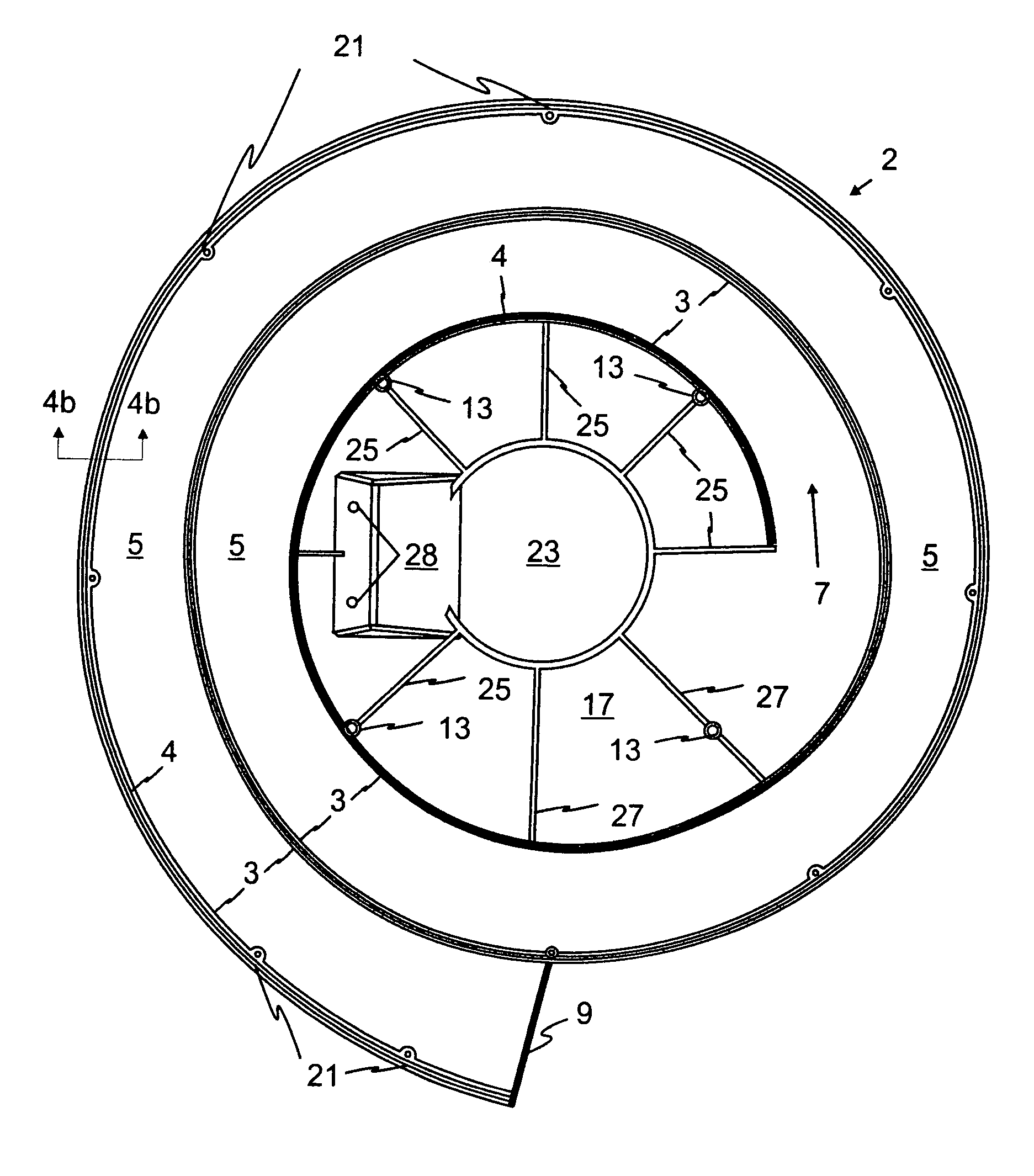
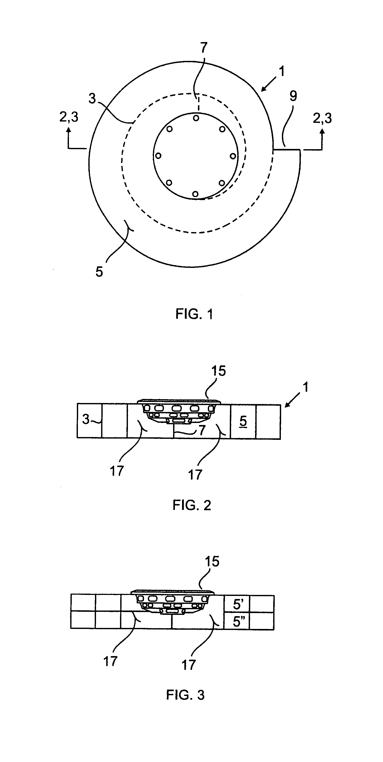
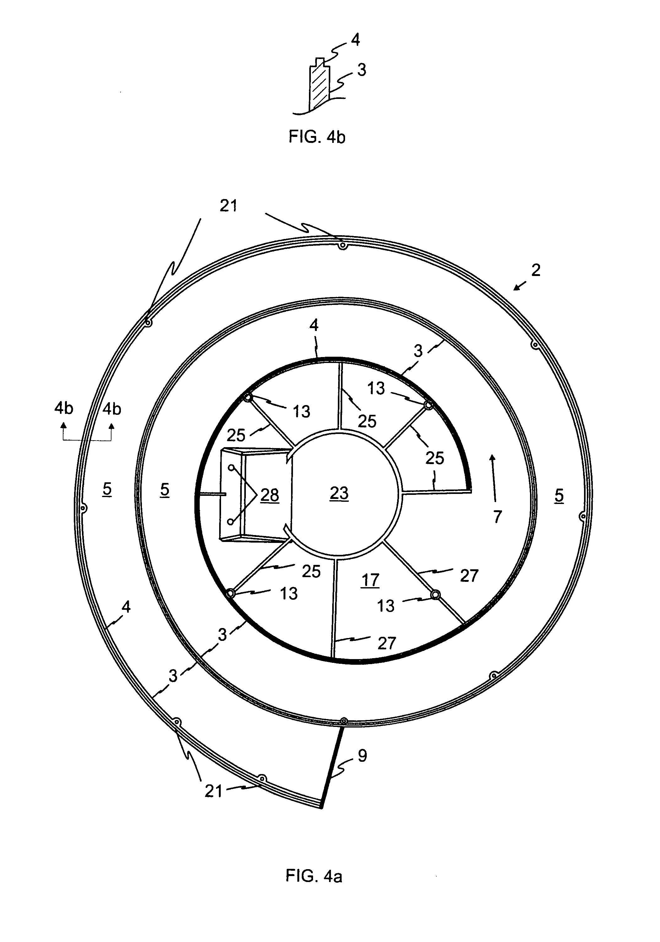
[0013]The present invention includes a compact quarter wavelength transmission path in the shape of a closed spiral that extends radially outward from a centrally located loudspeaker mounting location. The height of the transmission path has a minimum height that is equal to the height of the basket of the desired speaker. The quarter wavelength transmission path spiral of the present invention provides an aerodynamic path for air flow therein which reduces the turbulence of air flow to a minimum that in turn provides even resistance to the air flow (Exhale Vs Inhale).
[0016]The quarter wave speaker enclosure of the present invention is designed to receive a speaker with the axis of movement of the center of the cone oriented perpendicular to the outward expanding radius of the spiral shaped transmission tunnel which yields an enclosure that has a height that is slightly taller than the height of the basket of the speaker that is to be used with the enclosure. With the easy availability of low profile woofer speakers, the quarter wave speaker enclosure of the present invention can have an overall height of only a few inches which cannot be said for the prior art enclosures even if they incorporate a low profile speaker. Additionally, since the enclosure of the present invention is dictated by the shape of the transmission line, the ratio of the volume of the enclosure in comparison to the volume of the air within the transmission line is approximately unity. Further, an enclosure of the present invention that is designed for use with a 12 inch diameter speaker that is compensated for 56 Hz, the maximum diameter of the enclosure is approximately 24 inches, or twice the diameter of the speaker since the diameter of the speaker and the enclosure are in the same plane.

Problems solved by technology

Without a speaker enclosure any sound waves emanating from the rear of the speaker that are out of phase with the desired sound waves from the front of the speaker can create interference patterns and can cause cancellation of some frequencies in the desired sound waves.
This can be a major problem at lower frequencies where the wavelengths are longest.
It has been noted that at the lower frequencies the interference from sound waves from the back of the speaker can affect an entire listening area.
For those designs the enclosure volume relative to the port volume compromised the performance as the necessary shape of the port contributed to the non-linearity developed since the air resistance of the port (inhale vs exhale) are different.
Another problem of the prior art is the inconvenience of creating the “elephant's trunk” design in a traditional speaker enclosure.
This only introduced detrimental side effects, such as driver offset that worsened harmonics.
Another issue with the quarter wavelength designs of the prior art is extremely high harmonic distortions.
Additionally, the bottom of the second cylinder is separated from the bottom of the enclosure thus permitting some of the air mass from the fourth portion of the port to collect beneath the second cylinder thus causing yet additional turbulence in the air mass just before exiting the bottom of the enclosure.
This design has similar turbulence problems to those of his FIG. 1 design, plus an added problem.

Method used


Image

  • Loudspeaker low profile quarter wavelength transmission line and enclosure and method
  • Loudspeaker low profile quarter wavelength transmission line and enclosure and method
  • Loudspeaker low profile quarter wavelength transmission line and enclosure and method

Examples


Embodiment Construction

[0028]FIG. 1 shows a simplified top view of enclosure 1 that is configured substantially by the design of the enclosed quarter wavelength transmission line of the present invention. In the present invention the shape of the quarter wavelength transmission line determines the shape of the enclosure, the direct opposite of the prior art. The fact that the transmission line determines the enclosure shape one can think of the enclosure and the transmission line as being one and the same, thus reference number 1 may be used for both.

[0029]FIG. 1 further shows transmission line tunnel wall 3 as a broken line for the covered portion and as a solid line for the outer most portion of the wall, to illustrate the interior spiral shaped tunnel 5 that defines the transmission line length. The input of tunnel 5 is illustrated by broken line 7 and the output by solid line 9 at the outer most end of tunnel 5. Center hole 11 in the top cover is the location through which the included speaker (see FI...


PUM


Abstract

A speaker enclosure including a compact quarter wavelength transmission path in the shape of a closed spiral that expands radially outward from a centrally located loudspeaker mounting location. The height of the transmission path has a minimum height that is equal to the height of the basket of the desired speaker. The quarter wavelength transmission path spiral of the provides an aerodynamic path for air flow therein which reduces the turbulence of air flow to a minimum that in turn provides even resistance to the air flow within the transmission line (Exhale vs. Inhale).

Description

BACKGROUND OF THE INVENTION[0001]1. Field of the Invention[0002]The present invention relates to speaker systems that employ a quarter wavelength acoustic standing wave transmission line in combination with a speaker. More particularly, loudspeakers with a compact quarter wavelength transmission line and design methods associated with them.[0003]2. Description of the Prior Art[0004]Enclosures have been used with loudspeakers not simply to improve the appearance and decorative appearance of the speaker. Without a speaker enclosure any sound waves emanating from the rear of the speaker that are out of phase with the desired sound waves from the front of the speaker can create interference patterns and can cause cancellation of some frequencies in the desired sound waves. This can be a major problem at lower frequencies where the wavelengths are longest. It has been noted that at the lower frequencies the interference from sound waves from the back of the speaker can affect an entire l...

Claims


Application Information

Patent Timeline
Patent Type & Authority Patents(United States)
IPC IPC(8): G10K11/00
CPCH04R1/2857
Inventor SAHYOUN, JOSEPH Y.
Owner EARTHQUAKE SOUND
Learn More