Continuously variable transmission and engine

a transmission and variable technology, applied in the direction of friction gearings, belts/chains/gearings, friction gearings, etc., can solve the problems of not being able to allow engine braking or pushing starting of the engine, and the ball slipping between the inner and outer rings, so as to improve the lubrication construction

Inactive Publication Date: 2007-10-23
YAMAHA MOTOR CO LTD
View PDF12 Cites 117 Cited by
  • Summary
  • Abstract
  • Description
  • Claims
  • Application Information

AI Technical Summary

Benefits of technology

[0019]Thus, a ball-type continuously variable transmission is desired that allows engine braking and push-starting. A ball-type continuously variable transmission also is desired that features an improved lubrication construction.

Problems solved by technology

However, the arrangement disclosed in the Japanese reference described above is not believed to allow engine braking or push starting of the engine.
For example, when a driving force is applied to the output shaft of the ball-type continuously variable transmission from the driven wheel, the driven rollers press the balls, which causes the balls to slip between the inner and outer rings.

Method used


Image

  • Continuously variable transmission and engine
  • Continuously variable transmission and engine
  • Continuously variable transmission and engine

Examples


Embodiment Construction

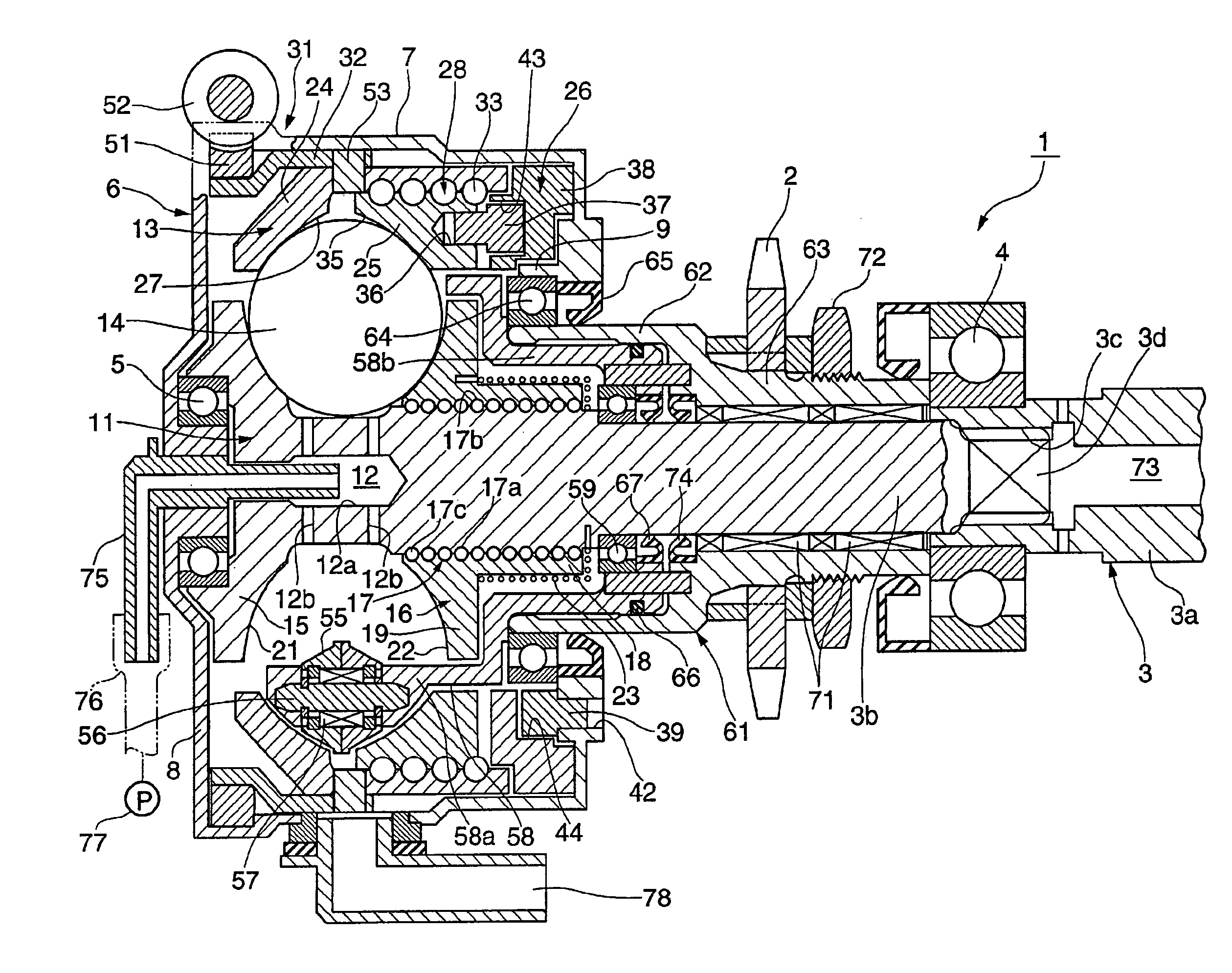
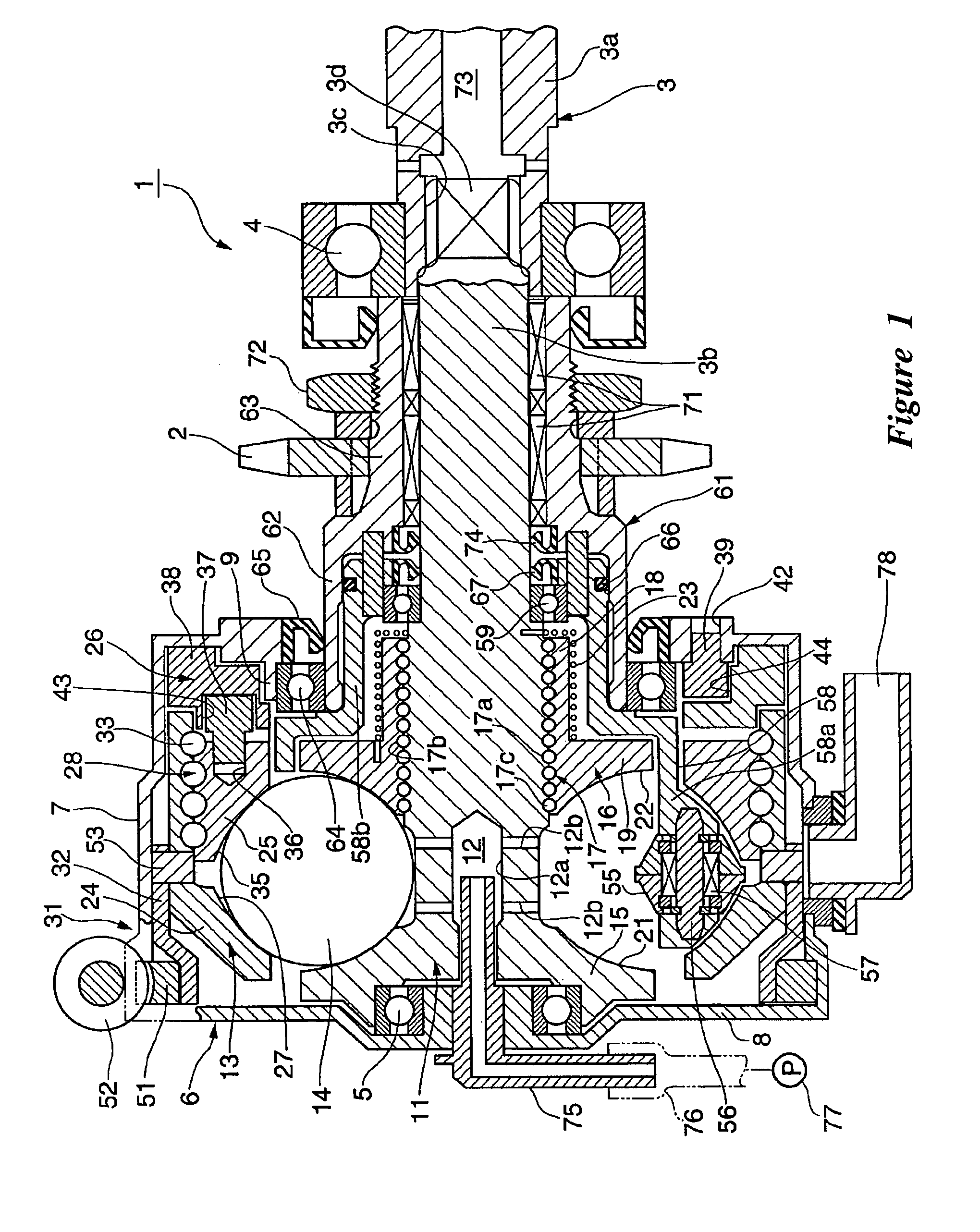
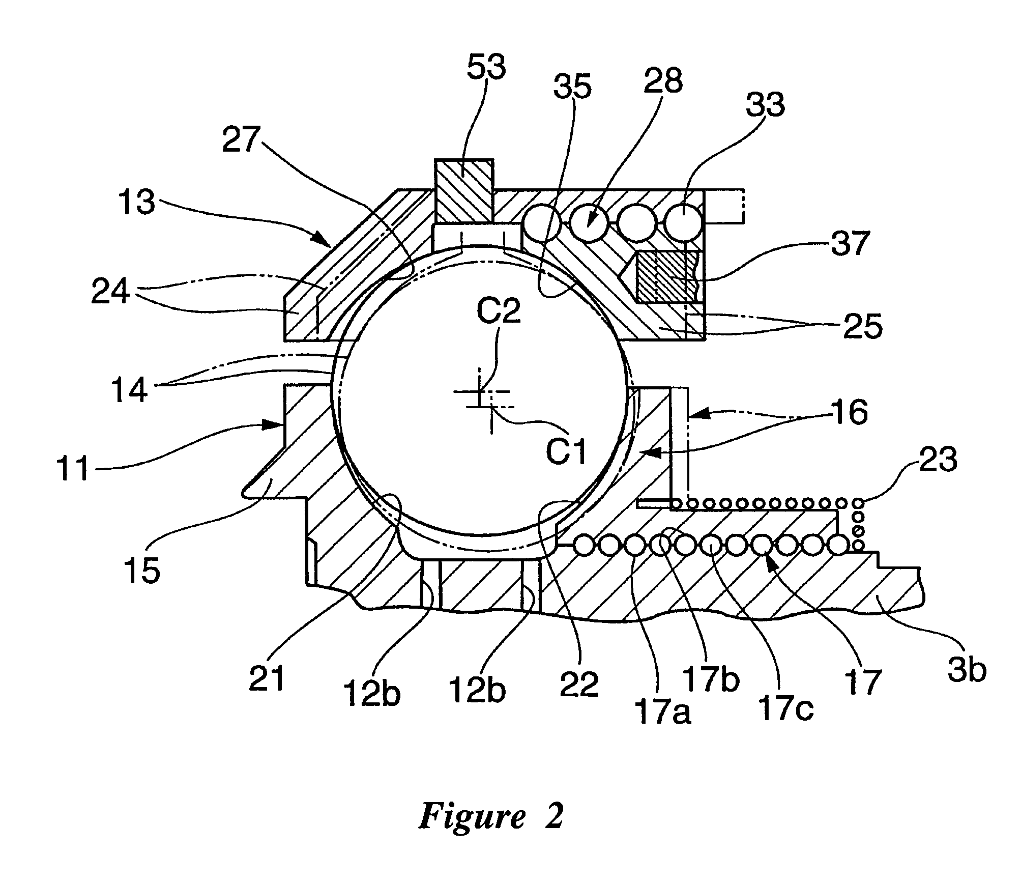
[0040]With reference now to FIGS. 1-9, an embodiment of a continuously variable transmission 1 that is arranged and configured in accordance with certain features, aspects and advantages of the present invention is illustrated. The continuously variable transmission 1 can be interposed between a clutch of an engine for a motorcycle (not shown) and a chain sprocket 2 for driving a rear wheel. In most configurations, the clutch has an input part in meshing engagement with a crankshaft and an output part that can be coupled to and uncoupled from the input part. The clutch also has a clutch shaft. In the illustrated embodiment, the clutch shaft is shown as an engine drive shaft.

[0041]The clutch shaft preferably is disposed generally parallel to the crankshaft and can be in meshing engagement with an input shaft 3 of the continuously variable transmission 1 via a speed reduction gear (not shown). The input shaft 3 may comprise the clutch shaft itself. In such a configuration, the continu...


PUM


Abstract

A continuously variable transmission features an inner ring and an outer ring. Each of the inner ring and the outer ring is split into a first portion and a second portion. At least two balls are positioned between the inner ring and the outer ring. The at least two balls also are positioned between the first and second portions of the inner and outer ring. The at least two balls rotate with rotation of the input shaft. As the distance between the first and second portions of the outer ring changes, the at least two balls move to a smaller radius of travel or a larger radius of travel. The rotation of the balls is transmitted to an output shaft. The input shaft and the output shaft are directly connectable through a one-way clutch to allow engine braking and / or push starting of the associated engine. A dedicated lubrication system also can be provided.

Description

CROSS-REFERENCE TO RELATED APPLICATIONS[0001]This application is based upon Japanese Patent Application No. 2004-214381, which was filed on Jul. 22, 2004 and which is hereby incorporated by reference in its entirety.BACKGROUND OF THE INVENTION[0002]1. Field of the Invention[0003]The present invention generally relates to a continuously variable transmission. More particularly, the present invention relates to a small vehicle, such as a motorcycle or small all-terrain four-wheel vehicle, for example, having a continuously variable transmission.[0004]2. Description of the Related Art[0005]In small scooter-style motor vehicles, a rubber V-belt continuously variable transmission is used to transmit power from an engine to the drive wheel. The rubber V-belt is entrained around a driving pulley, which is mounted to the crankshaft, and a driven pulley, which is in mechanical communication with the drive wheel, which is usually the rear wheel. The power of the engine is transmitted to the r...

Claims


Application Information

Patent Timeline
Patent Type & Authority Patents(United States)
IPC IPC(8): F16H15/48
CPCF16H15/503
Inventor HOSOI, YUKIHARU
Owner YAMAHA MOTOR CO LTD
Why Eureka
Try Eureka