Control method and electronic device enabling recognition of functions installed in the electronic device

a control method and electronic device technology, applied in the direction of program control, input/output to record carriers, instruments, etc., can solve problems such as complicated procedures, and achieve the effects of convenient recognition of functions installed in electronic devices, reliable execution, and reliably enabling a desired function

Inactive Publication Date: 2007-10-23
SONY CORP
View PDF10 Cites 0 Cited by
  • Summary
  • Abstract
  • Description
  • Claims
  • Application Information

AI Technical Summary

Benefits of technology

[0009]According to the present invention, it is possible to enable a main unit to recognize a function to be executed by an electronic device, and hence a desired function is reliably executed by using a simple method. The main unit can reliably enable a desired function. Also, the main unit can easily recognize a function installed in the electronic device. It is therefore possible to prevent unnecessary operations and malfunctions such as the activation of an unexecutable function. Even when a list of functions is not provided, it is still possible to prevent unnecessary operations and malfunctions such as the activation of an unexecutable function. As a result, the present invention can solve problems encountered with a conventional electronic device. Such problems include erroneous processing and main unit malfunctions due to the main unit's inability to recognize a function to be executed by the electronic device, which may require time and a complicated procedure to restore the main unit to its original state.

Problems solved by technology

Such problems include erroneous processing and main unit malfunctions due to the main unit's inability to recognize a function to be executed by the electronic device, which may require time and a complicated procedure to restore the main unit to its original state.

Method used


Image

  • Control method and electronic device enabling recognition of functions installed in the electronic device
  • Control method and electronic device enabling recognition of functions installed in the electronic device
  • Control method and electronic device enabling recognition of functions installed in the electronic device

Examples


Embodiment Construction

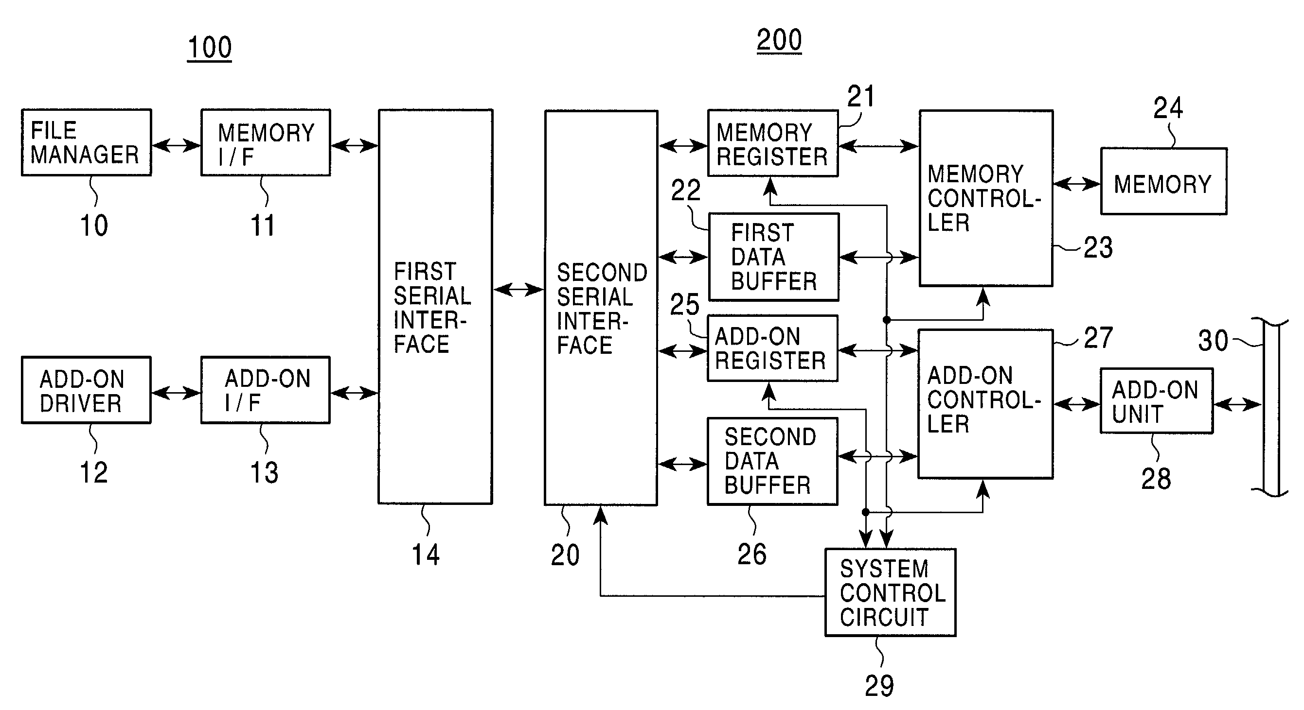
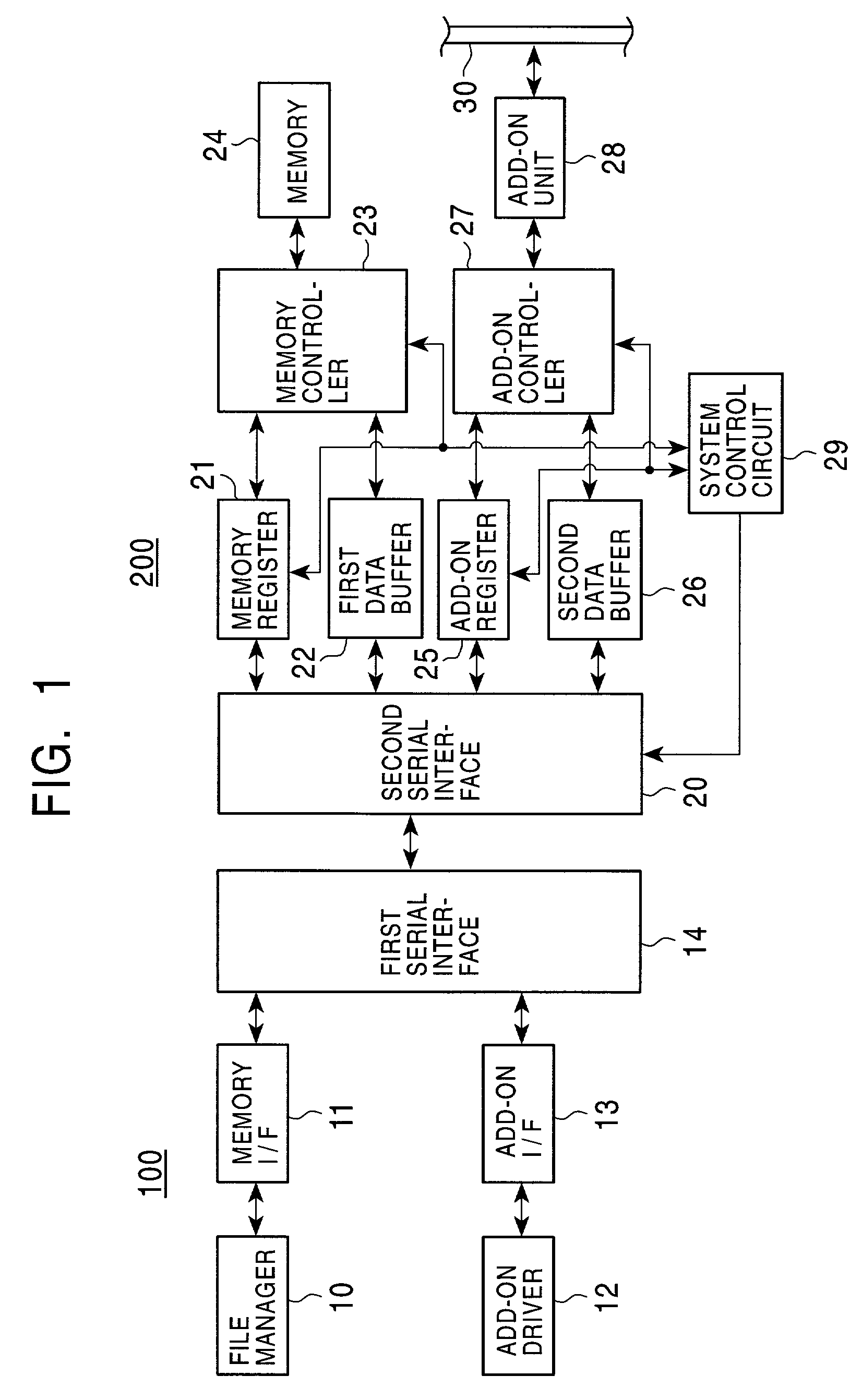
[0017]The present invention will become apparent from the following description of the preferred embodiment with reference to the accompanying drawings. FIG. 1 is a block diagram of an electronic device and a main unit according to an embodiment of the present invention.

[0018]Referring to FIG. 1, a main unit 100 is illustrated at the left of the block diagram. A data file stored in a memory device (not shown) or the like provided in the main unit 100 is exchanged with a memory interface (I / F) 11 through a file manager 10. An add-on driver 12 is provided for performing an arbitrary extended function. Data in the add-on driver 12 is exchanged with an add-on interface 13. Data in the memory interface 11 and the add-on interface 13 is exchanged with a first serial interface 14.

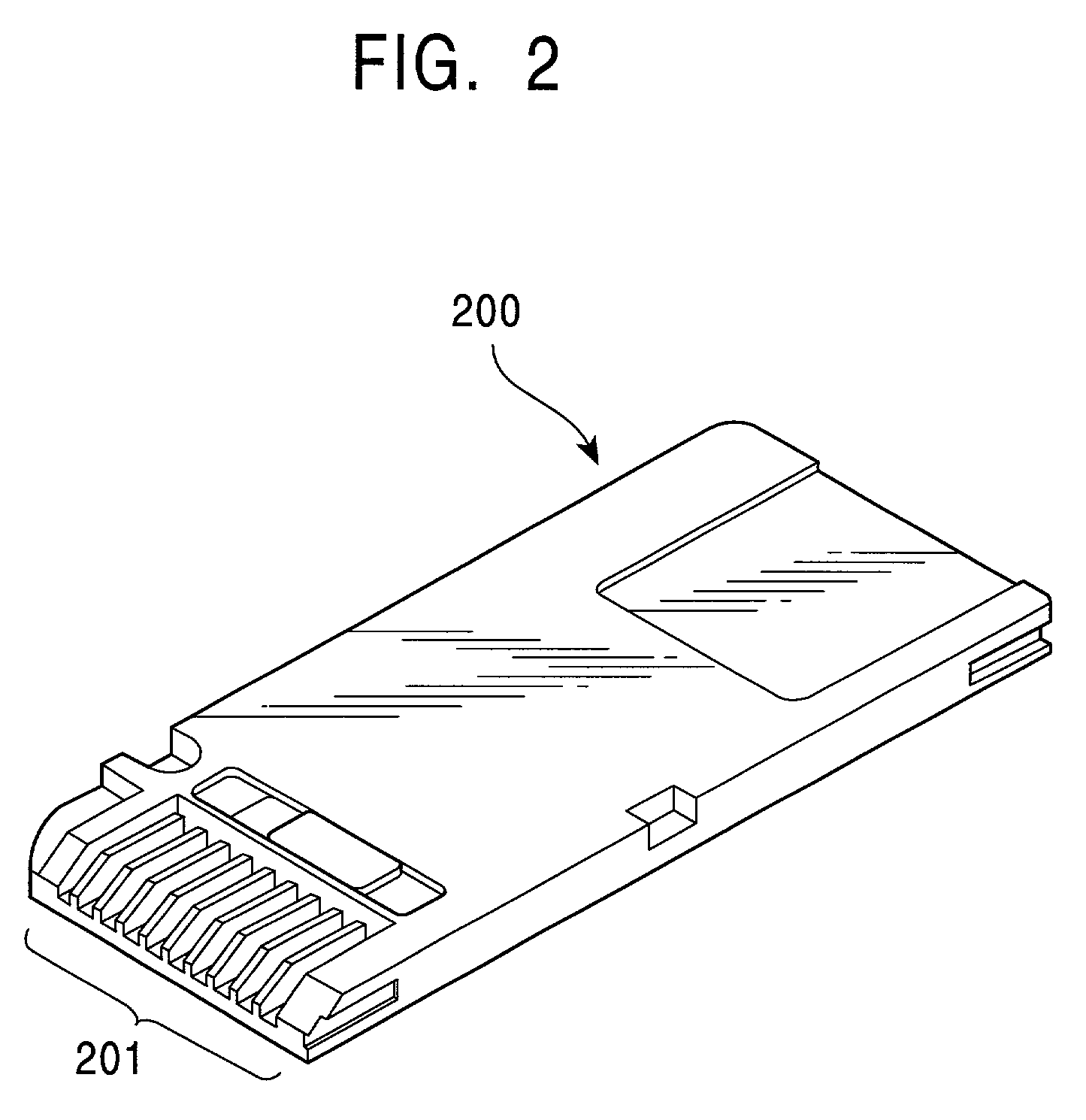
[0019]At the right of the block diagram, an electronic device 200 is shown. Referring to FIG. 2, for example, the electronic device 200 has an equivalent shape to a so-called memory card or a semiconductor memory ...


PUM


Abstract

An electronic device includes a serial interface which exchanges data with a memory register and a first data buffer. In accordance with a setting which is written in the memory register, data in the first data buffer is exchanged with a memory through a memory controller. The serial interface exchanges data with an add-on register and a second data buffer. In accordance with a setting which is written in the add-on register, data in the second data buffer is exchanged with an add-on unit through an add-on controller. The add-on unit is connected to an external LAN or the like. Part of the setting data written in the memory register and the add-on register is determined from the add-on unit by a system control circuit. In accordance with the determination, a function to be executed by the electronic device is changed.

Description

CROSS-REFERENCE TO RELATED APPLICATIONS[0001]The present invention claims priority from Japanese Application Nos. P2000-111030 filed Apr. 12, 2000 and P2001-058598 filed Mar. 2, 2001, the disclosures of which are hereby incorporated by reference herein.BACKGROUND OF THE INVENTION[0002]The present invention relates to control methods and electronic devices suitable for being used as, for example, devices which are removably provided with respect to a main unit in order to perform arbitrary functions. More particularly, the present invention relates to a control method and to an electronic device which has an equivalent shape to a memory card or a similar semiconductor memory and which is connected to the memory connecting section of the main unit in order to perform arbitrary functions.[0003]For example, an electronic device may have an equivalent shape to a memory card which is removable from a main unit or to a similar semiconductor memory. The electronic device is connected to the...

Claims


Application Information

Patent Timeline
Patent Type & Authority Patents(United States)
IPC IPC(8): G06F3/00G06F13/00G06K19/07G06F3/08G06F9/38G06K17/00
CPCG06F9/3879
Inventor KUBOTA, YOSHIYASU
Owner SONY CORP
Why Eureka
Try Eureka