Method for selecting printing material in a printing press and printing press

a printing press and printing press technology, applied in printing presses, office printing, printing, etc., can solve the problems of short power failure, power supply, and the printing speed of the printing press likewise begins to fluctua

Inactive Publication Date: 2007-10-30
HEIDELBERGER DRUCKMASCHINEN AG
View PDF17 Cites 25 Cited by
  • Summary
  • Abstract
  • Description
  • Claims
  • Application Information

AI Technical Summary

Benefits of technology

[0006]It is accordingly an object of the invention to provide a method for selecting printing materials in a printing press and to a printing press that overcomes the above-mentioned disadvantages of the prior art devices and methods of this general type, which permits the most precise forecast possible of rejects that occur during a printing operation.
[0015]In an alternative refinement of the invention, provision is made for the sheet printing materials registered by the control computer to be separated from further sheet printing materials by a tab inserter. It is therefore possible to dispense with a sheet diverter and nevertheless to separate reject sheets from the good sheets. In this case, this separation of the reject sheets takes place in the deliverer stack, a tab being inserted into the deliverer stack in each case before and after the reject sheet or sheets. Thus, the reject sheets are always located between two inserted tabs and can be separated easily from the good sheets in the deliverer stack.

Problems solved by technology

Disturbances in the power supply can be in particular mains fluctuations but also short power failures.
The mains fluctuation and power failures necessarily have an effect on the electric drive motors of the printing press.
These in turn influence the printing operation since, as a result, the printing speed of the printing press likewise begins to fluctuate.
A fluctuating printing speed always ensures an increased susceptibility to rejects, however, so that it is expedient to register those sheets during whose production time corresponding fluctuations have occurred in the power supply.
Not every fluctuation in the power supply must simultaneously necessarily lead to a change in the printing speed of the printing press, since the printing press represents a rather sluggish oscillatory system because of the high rotating masses.

Method used


Image

  • Method for selecting printing material in a printing press and printing press
  • Method for selecting printing material in a printing press and printing press
  • Method for selecting printing material in a printing press and printing press

Examples


Embodiment Construction

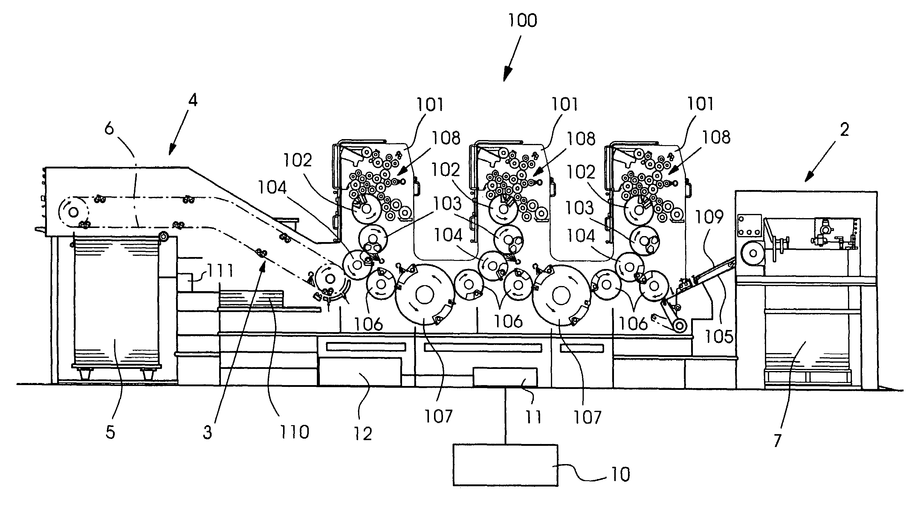
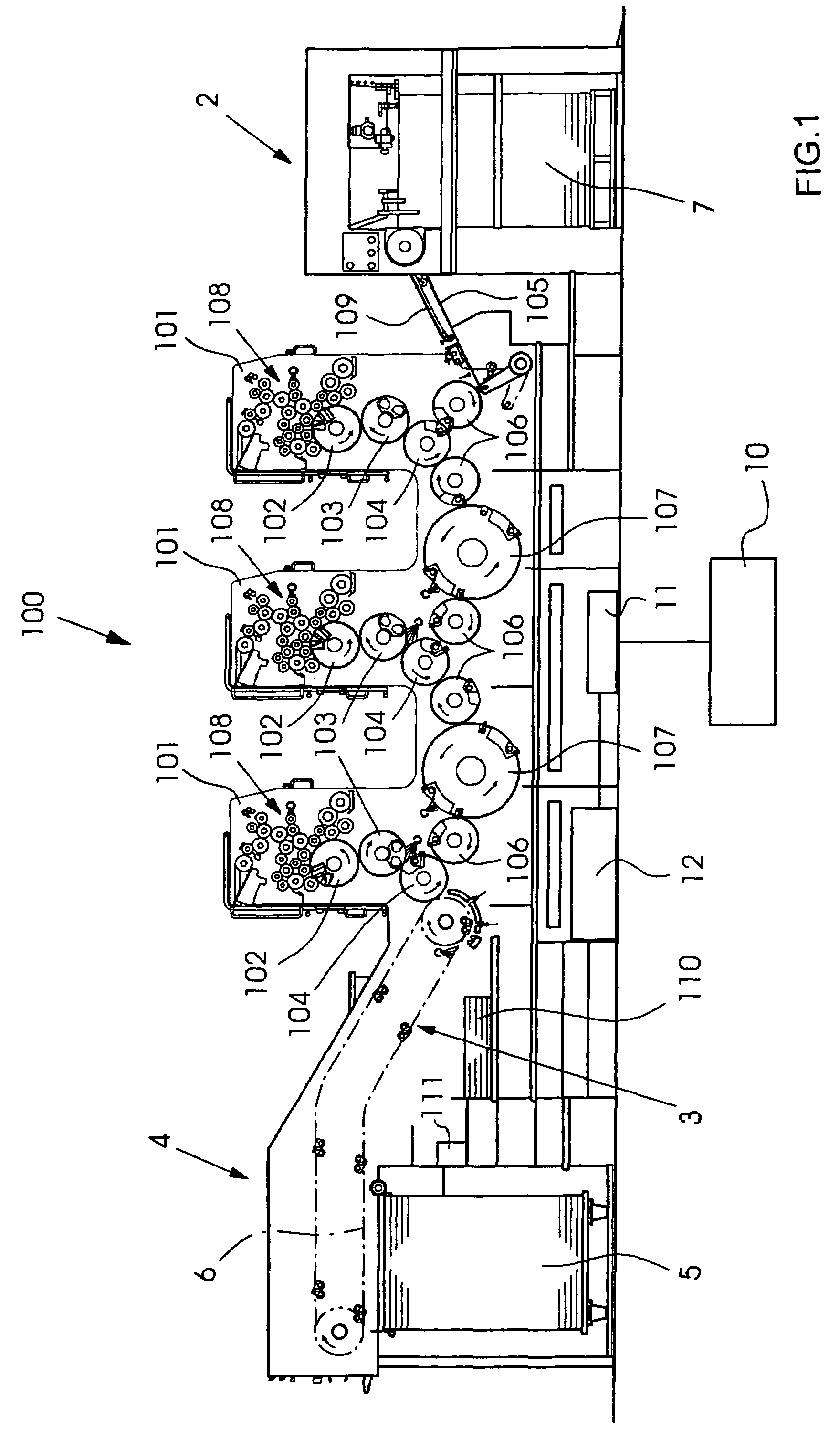
[0021]Referring now to the figures of the drawing in detail and first, particularly, to FIG. 1 thereof, there is shown a sheetfed rotary printing press 100 which has a three printing units 101. Each of the three printing units 101 has an inking unit 108 which supplies the cylinders of the respective printing unit 101 with ink and damping solution. From the inking unit 108, the printing ink reaches the plate cylinder 102, which in turn transfers a printing image to a blanket cylinder 103. The blanket cylinder 103 transfers the printing image to a sheet 109 to be printed, which is transported through in the press nip between the blanket cylinder 103 and an impression cylinder 104. This procedure proceeds in each of the printing units 101, so that, as it runs through the printing press 100, the sheet is gradually printed with all the color separations. At the start of the printing press 100, the sheets 109 are removed from a feeder stack 7 and separated in the feeder 2. The separated p...


PUM


Abstract

An apparatus and a method for the selection of printing materials in a machine processing printing materials has at least one control computer. The operating data of the machine processing the printing materials is logged by the computer and a tolerance limit corresponding to the operating data registered is stored in the computer. When the tolerance limit is exceeded during a time interval, the printing materials produced in this time interval are registered in the control computer.

Description

CROSS-REFERENCE TO RELATED APPLICATION[0001]This application claims the priority, under 35 U.S.C. §119, of German application DE 10 2005 060 889.2, filed Dec. 20, 2005; the prior application is herewith incorporated by reference in its entirety.BACKGROUND OF THE INVENTIONField of the Invention[0002]The invention relates to a method for the selection of printing materials in a machine processing printing materials and having at least one control computer. The operating data of the machine processing printing materials is logged by the computer and a tolerance limit corresponding to the operating data registered is stored in the computer.[0003]The operation of a printing press is all the more economic when the fewest unusable prints are produced. The unusable prints are designated rejects and arise in particular when starting up a printing press or after a job change, since here the entire printing press first has to be transferred to a stable operating state until the printing qualit...

Claims


Application Information

Patent Timeline
Patent Type & Authority Patents(United States)
IPC IPC(8): B41F33/00
CPCB41F33/0009
Inventor KLEIBAUMHUTER, KLAUS-DIETERMEYER, HELMUTSCHMITT, KARLHEINZ
Owner HEIDELBERGER DRUCKMASCHINEN AG
Why Eureka
Try Eureka