Filling system for an anesthetic evaporator

a filling system and anesthetic technology, applied in the direction of liquid transfer devices, liquid handling, packaging goods types, etc., can solve the problem of relatively complicated valve design

Active Publication Date: 2007-10-30
DRAGERWERK AG
View PDF8 Cites 12 Cited by
  • Summary
  • Abstract
  • Description
  • Claims
  • Application Information

AI Technical Summary

Benefits of technology

[0010]The advantage of the present invention is essentially that the opening mechanisms for the adapter valve and the filling valve are completely uncoupled. Instead of a centrally arranged, stationary bar, which is passed through the filling valve at the filling device, at least one stationary bar, which actuates the adapter valve via a laterally longitudinally extending slot or a plurality of slots at the outlet pipe of the bottle adapter, is arranged at the inner wall of the filler neck. It is thus possible to design especially the filling valve as a simple lifting valve, which is not compromised by additional functions. In addition, it is possible to cover the front side of the outlet pipe in order to prevent the adapter valve from being damaged. Due to the arrangement according to the present invention of a stationary bar, which is attached to the inner wall of the filler neck and points radially toward the center of the filler neck, only a longitudinally extending slot, which can be engaged by the bar in order to actuate the adapter valve, needs to be provided at the outlet pipe of the bottle adapter. The outlet pipe can thus have an especially robust design in order to protect the adapter valve against possible damage.
[0011]The anesthetic-specific coding is advantageously designed as a polygon. For example, a hexagon may thus be selected as the polygon for the anesthetic halothane, a regular pentagon for enflurane, and a regular heptagon for isoflurane. Thus, no special preferred position is to be complied with for introducing the bottle adapter into the filling device, but the introduction position can be found by slightly rotating the bottle adapter in relation to the filling device. An outer polygon is located on the bottle adapter, and an inner polygon, into which the outer polygon can be introduced like a wrench, is arranged within the filler neck.
[0012]It is especially advantageous to design the bar as a spoked wheel and to provide corresponding slots on the outlet pipe of the bottle adapter corresponding to the spoked wheel. The spoked wheel comprises individual bars, which are directed toward the center of the filler neck. As an alternative to the polygon or even in addition to the polygon, an anesthetic-specific coding can be embodied by selecting the number of bars in the spoked wheel or by selecting their angular positions in relation to one another. The fact that the valve piston of the adapter valve is lifted uniformly is also an advantage of a spoked wheel compared to an individual bar.
[0013]Connecting the bottle adapter rigidly to the storage container for liquid anesthetics is also within the scope of the present invention.
[0014]An exemplary embodiment of the present invention is shown in the figure and will be explained in greater detail below. The various features of novelty which characterize the invention are pointed out with particularity in the claims annexed to and forming a part of this disclosure. For a better understanding of the invention, its operating advantages and specific objects attained by its uses, reference is made to the accompanying drawings and descriptive matter in which a preferred embodiment of the invention is illustrated.

Problems solved by technology

The drawback of the prior-art filling system is that the stationary bar, with which the adapter valve is opened, and the filling valve are connected to one another as one assembly unit and can therefore mutually affect each other.
In addition, the design of the valve is relatively complicated.

Method used


Image

  • Filling system for an anesthetic evaporator
  • Filling system for an anesthetic evaporator
  • Filling system for an anesthetic evaporator

Examples


Embodiment Construction

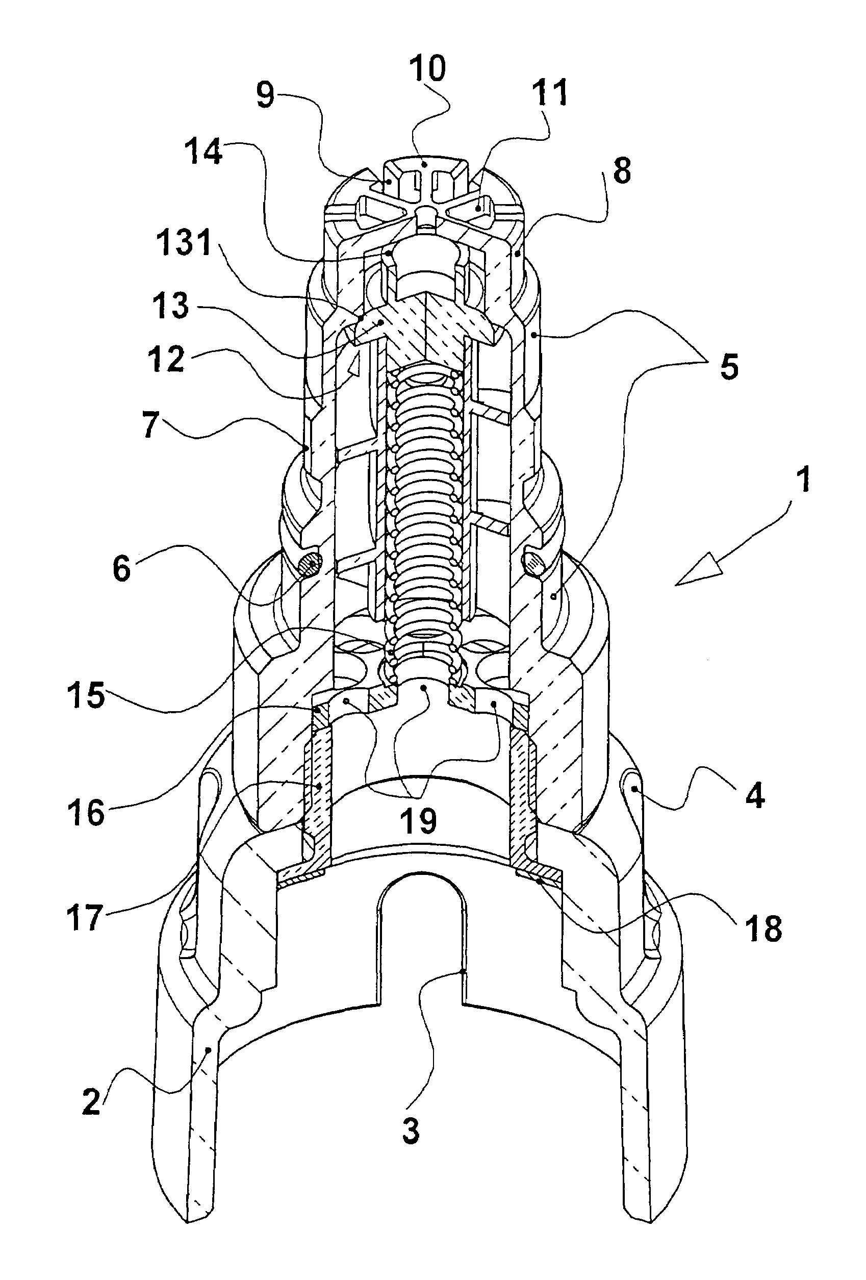
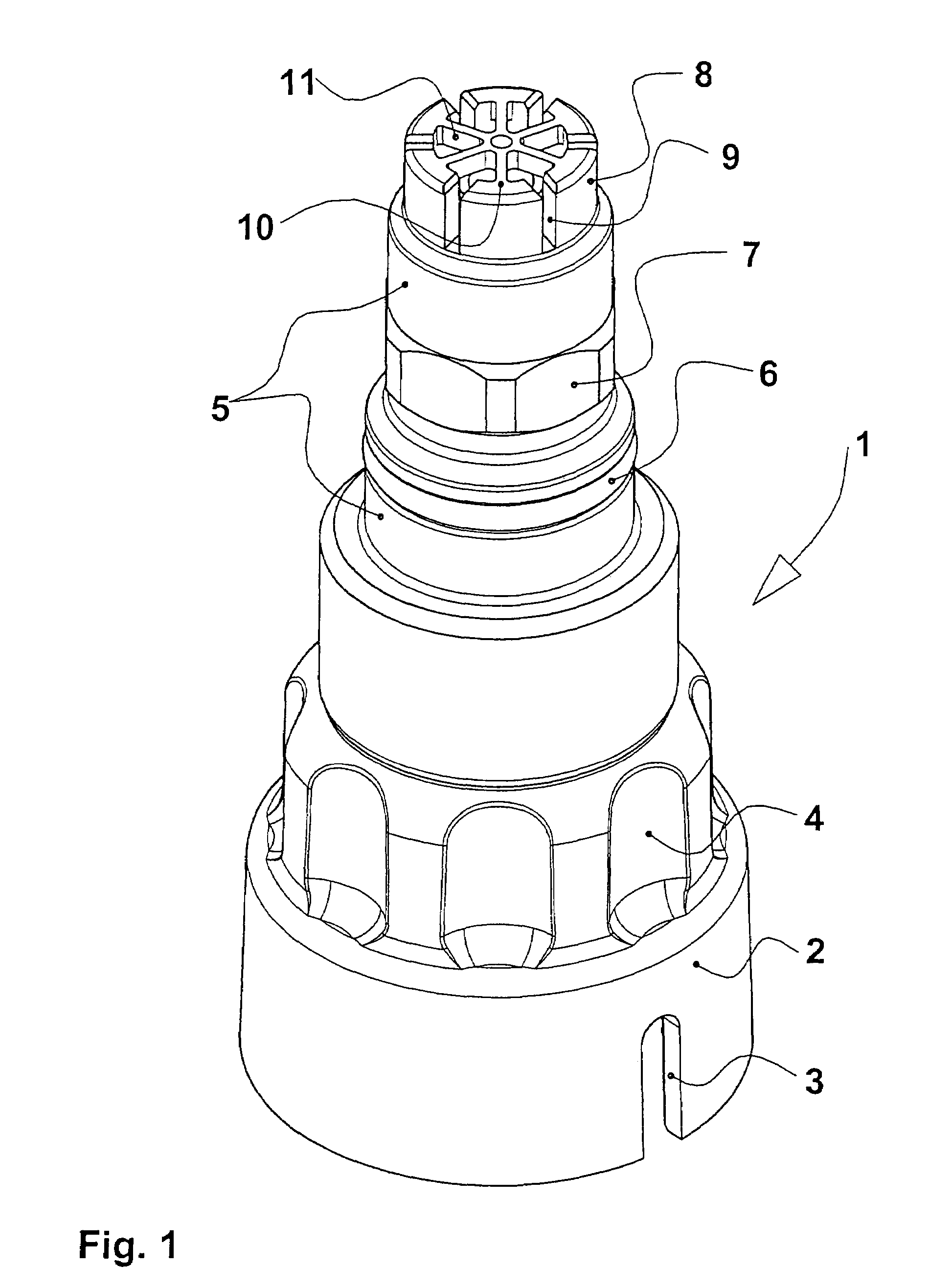
[0020]Referring to the drawings in particular, FIG. 1 shows a perspective view of a bottle adapter 1, which has a collet 2 on its underside for being screwed onto a storage container for liquid anesthetic, not shown in greater detail in FIG. 1. On its bottle collar, the storage container has an anesthetic-specific index collar, which is introduced into receiving grooves 3 of the collet 2. Thus, only a bottle adapter 1 that belongs to the anesthetic can be screwed onto the storage container. The screwing movement is facilitated by recessed grips 4 above the collet 2. An adapter neck 5 with an O-ring 6 and with an outer polygon 7 for the anesthetic-specific coding as well as an outlet pipe 8 with radially extending slots 9 are located at the top end of the bottle adapter 1. The top side 10 of the pipe is designed as a star 11.

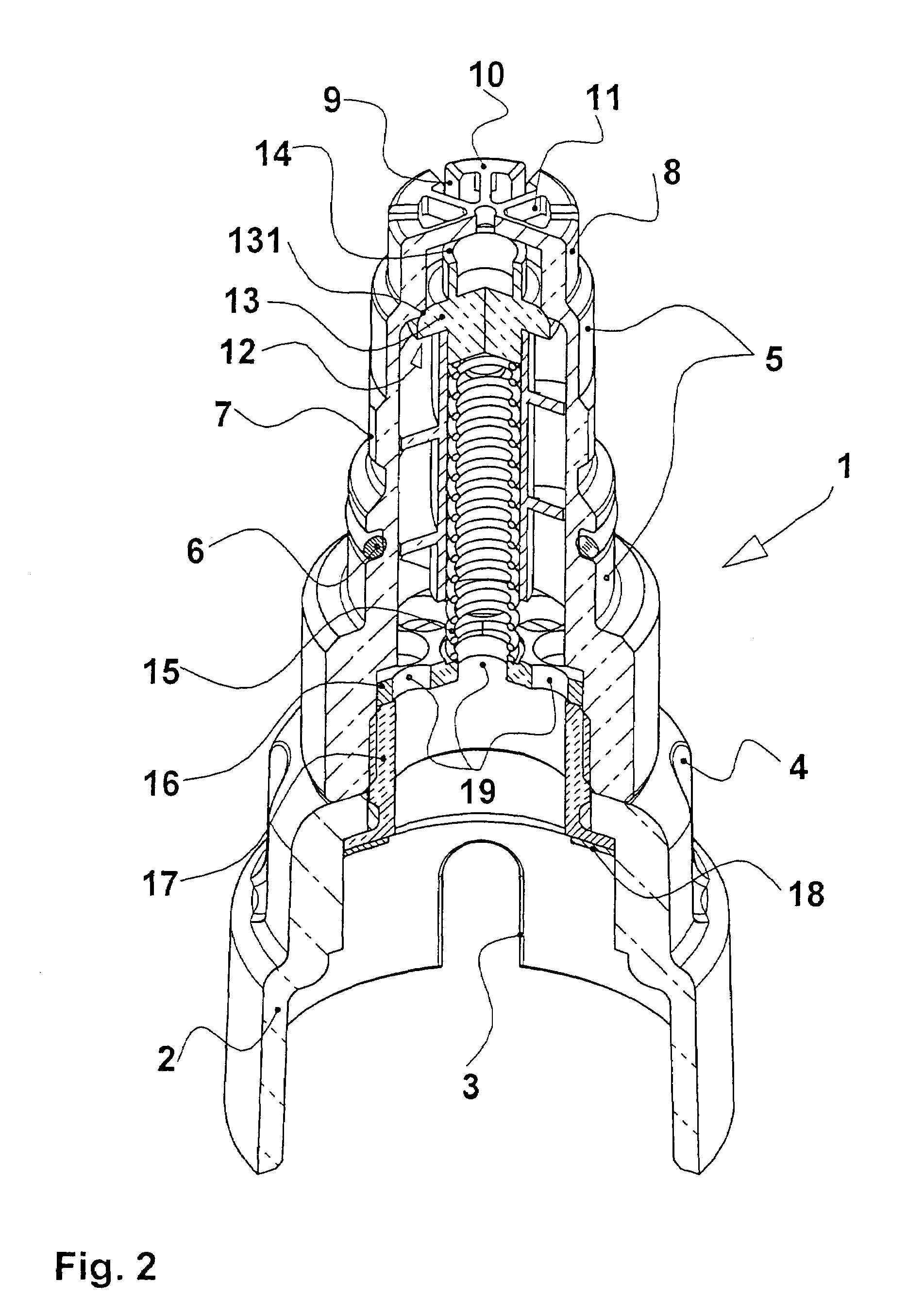
[0021]FIG. 2 illustrates the longitudinal view of the bottle adapter 1 according to FIG. 1. Identical components are designated by the same reference numbers as ...


PUM

PropertyMeasurementUnit
areaaaaaaaaaaa
depthaaaaaaaaaa
angleaaaaaaaaaa

Abstract

The interaction between a filling valve (28) on the filling device and an adapter valve on a bottle adapter has improved anesthetics filling features including radially inwardly directed bars (26), which engage (pass into) corresponding slots on the outlet pipe of the bottle adapter. The bars engaged in the slots actuate the adapter valve. The bars are provided on the inner wall of a filler neck (22).

Description

CROSS REFERENCE TO RELATED APPLICATIONS[0001]This application claims the benefit of priority under 35 U.S.C. § 119 of German Patent Application DE 10 2004 063 883.7 filed Dec. 21, 2004, the entire contents of which are incorporated herein by reference.FIELD OF THE INVENTION[0002]The present invention pertains to a filling system for an anesthetic evaporator.BACKGROUND OF THE INVENTION[0003]A filling system of the type mentioned has become known from U.S. Pat. No. 6,585,016 B1. To make it possible to fill liquid anesthetic into an anesthetic evaporator, a bottle adapter is necessary, which establishes the connection between the storage container for liquid anesthetic and the filling device at the anesthetic evaporator. A collet, which has two grooves for receiving an index collar arranged at the neck of the storage container, is provided at the bottle-side end of the bottle adapter. The index collar has an anesthetic-specific design, so that only the bottle adapter fitting the storag...

Claims


Application Information

Patent Timeline
Patent Type & Authority Patents(United States)
IPC IPC(8): B65B1/04B67D7/32B67D7/54
CPCA61M16/183
Inventor TURKER, AHMETREICHERT, DIRK-STEFANBUNKE, CLAUS
Owner DRAGERWERK AG
Why Eureka
Try Eureka