Rotary throttle valve carburetor

a technology of rotary throttle valve and carburetor, which is applied in the field of carburetors, can solve the problems of affecting the relative position of the valve valve, requiring a relatively high level of manufacturing technology and effort, etc., and achieves the effects of reducing the amount of assembly work, reducing manufacturing costs, and simplifying assembly

Inactive Publication Date: 2007-10-30
NIPPON WALBRO KK
View PDF15 Cites 10 Cited by
  • Summary
  • Abstract
  • Description
  • Claims
  • Application Information

AI Technical Summary

Benefits of technology

[0010]With the valve bore for rotatably receiving the throttle valve body and the throttle valve support both formed in the carburetor main body, the desired position and alignment of these two components can be easily controlled and repeatedly achieved, for instance by casting. Because a separate lid is not required, the number of necessary component parts and the amount of the assembly work can be reduced so that assembly is simplified and the manufacturing cost is reduced. Also, because a lid is not required with the carburetor, a cable retaining portion adapted to retain an outer sheath of a throttle cable can be integrally formed on the carburetor body. This facilitates accurate and repeatable positioning of the cable retaining portion relative to the throttle valve, and thereby facilitates assembly, manufacture and consistent operation of the throttle valve assembly.

Problems solved by technology

Because the carburetor main body and lid are manufactured and finished separately, it is necessary to join them together so that an opening in the lid that receives the throttle valve shaft is accurately coaxially aligned with the valve bore, and this requires a relatively high level of manufacturing technology and effort.
Some tolerance is required in the position of the lid on the carburetor body to facilitate manufacture and assembly of the carburetor, and this affects their relative position from one carburetor to another.

Method used


Image

  • Rotary throttle valve carburetor
  • Rotary throttle valve carburetor
  • Rotary throttle valve carburetor

Examples


Embodiment Construction

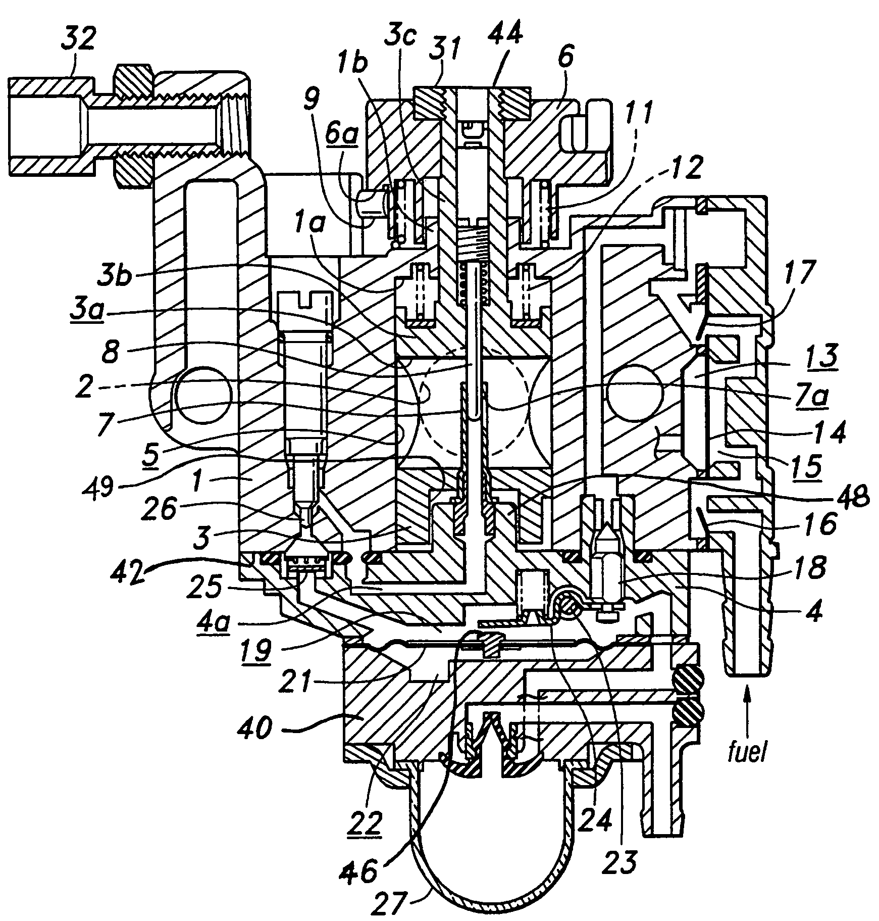
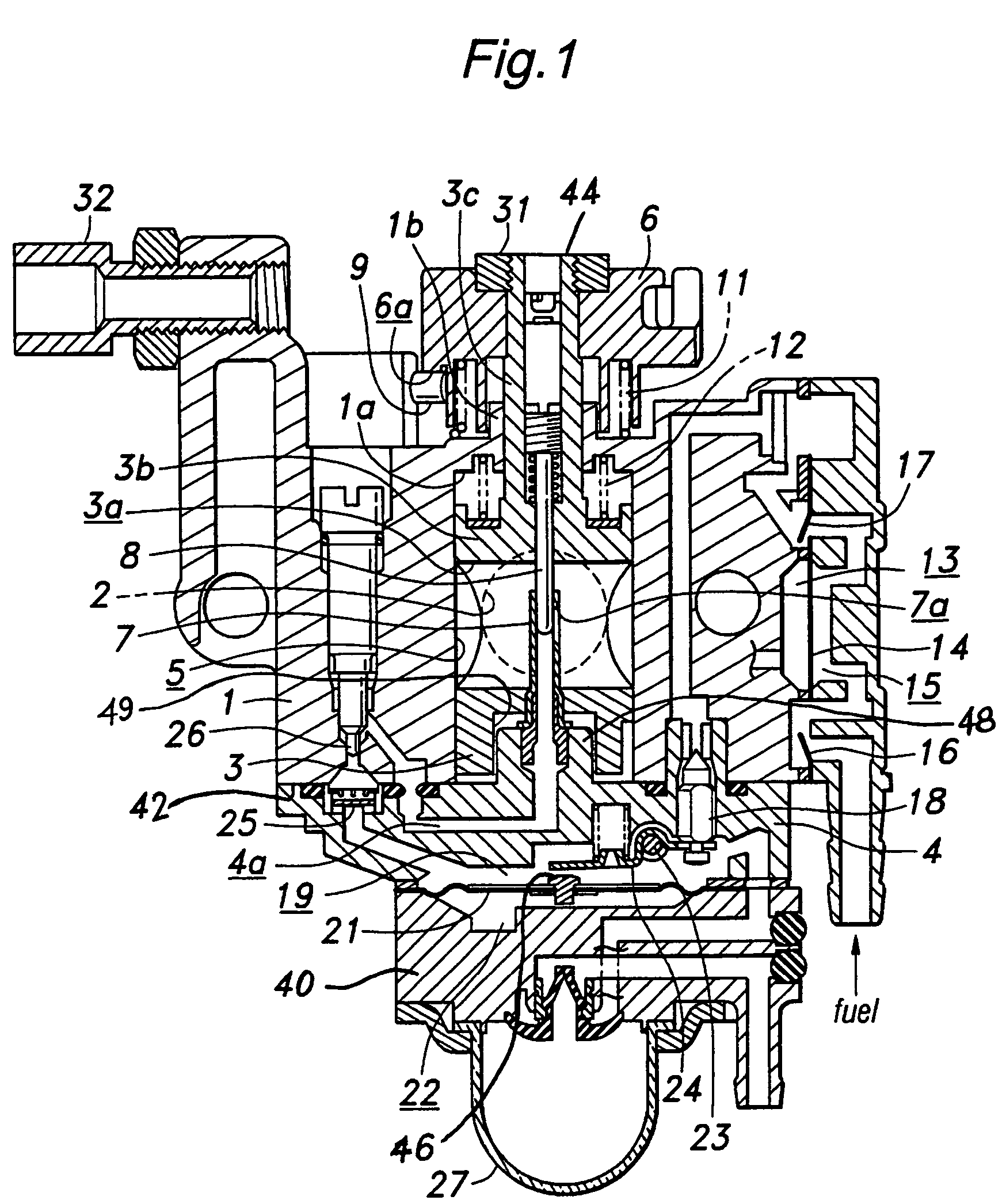
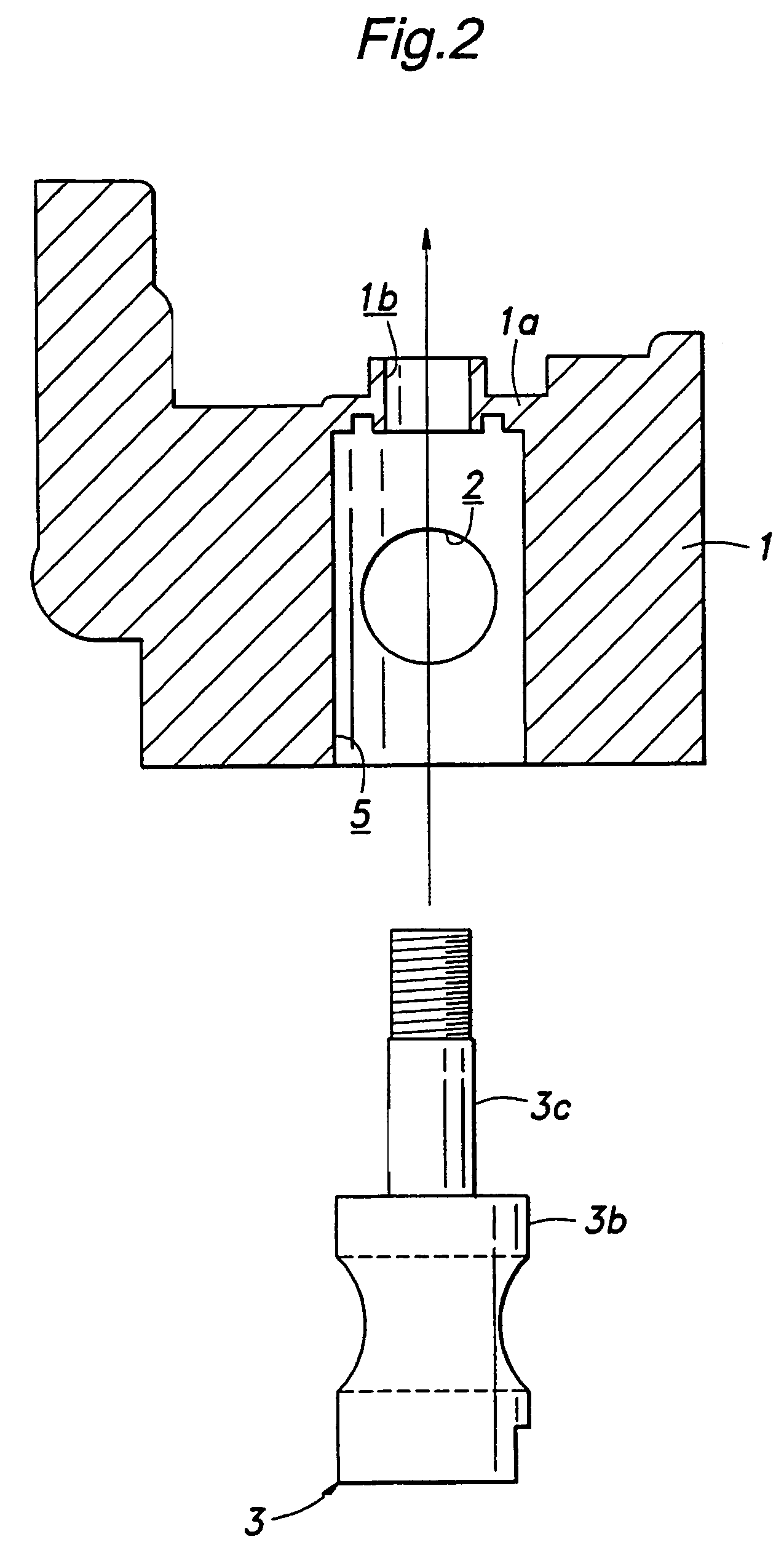
[0017]Referring in more detail to the drawings, FIG. 1 illustrates a rotary throttle valve carburetor that includes a carburetor main body 1 provided with a fuel and air mixing passage 2. Air enters the mixing passage 2 at one end, is mixed with fuel, and a fuel and air mixture flows out of an outlet end of the mixing passage 2 for delivery to an engine. The main body 1 also includes a valve bore 5 extending perpendicular to and communicated with the mixing passage 2. A rotary throttle valve 3 is placed in the valve bore 5 and includes an intake or valve passage 3a therethrough that is variably aligned or registered with the mixing passage 2 to selectively open and close the same. The main body 1 preferably is formed of cast metal, such as diecast aluminum, or by other suitable methods and materials known in the art.

[0018]A second carburetor body, such as a fuel chamber body 4, is attached to the lower end of the carburetor main body 1. A pump body 40 is attached to the fuel chamber...


PUM

PropertyMeasurementUnit
areaaaaaaaaaaa
pressureaaaaaaaaaa
flow rateaaaaaaaaaa

Abstract

A rotary throttle valve carburetor includes a main body defining a mixing passage and a valve bore, and a throttle valve rotatably received in the valve bore to selectively open and close the mixing passage. The carburetor main body includes an integral throttle valve support extending radially inwardly relative to the valve bore adjacent to a first end of the valve bore and a second end of the valve bore is open. A throttle cable retaining portion may also be integrally formed with the carburetor main body.

Description

REFERENCE TO RELATED APPLICATION[0001]Applicant claims priority of Japanese patent applications, Serial Nos. JP 2004-031692, filed Feb. 9, 2004 and JP 2004-065293, filed Mar. 9, 2004.[0002]1. Field of the Invention[0003]This invention relates generally to a carburetor and more particularly to throttle valve arrangement in a rotary throttle valve carburetor.[0004]2. Background of the Invention[0005]A conventional rotary throttle valve carburetor for use in small internal combustion engines such as lawn mowers, motor scooters and the like comprises a cylindrical rotary throttle valve with a valve passage that is selectively and variably registered with a mixing passage of the carburetor by rotating the throttle valve about an axis generally perpendicular to the mixing passage. A needle valve extends into the passage of the rotary valve, and a fuel nozzle projects into the mixing passage and slidably receives the tip of the needle valve.[0006]In such a rotary throttle valve carburetor,...

Claims


Application Information

Patent Timeline
Patent Type & Authority Patents(United States)
IPC IPC(8): F02M9/08
CPCF02M9/08Y10T29/49405
Inventor HORIKAWA, TAKASHITOBINAI, TERUHIKOTAKEZAWA, SUSUMUTAKANO, JUN
Owner NIPPON WALBRO KK
Why Eureka
Try Eureka