Vehicle suspension system and method

a suspension system and vehicle technology, applied in the direction of shock absorbers, cycle equipment, instruments, etc., can solve the problems of affecting vehicle performance, reducing performance, and a large amount of road or other inpu

Active Publication Date: 2007-10-30
DRIVERIGHT HLDG
View PDF44 Cites 119 Cited by
  • Summary
  • Abstract
  • Description
  • Claims
  • Application Information

AI Technical Summary

Problems solved by technology

It is well understood, however, that damping members undesirably transmit road and other inputs to the sprung mass of a vehicle, and that the level of damping action of the damping member has a relation to the amount or magnitude of the road input that is transmitted through the damping member to the sprung mass of the vehicle.
Typically, the more aggressive the damping action of the damping member, the greater amount of the road or other input that is transmitted to the sprung mass of the vehicle.
However, it is also well understood that vehicle performance is affected by the level of damping action of a suspension system and that better handling and / or performance is normally achieved at higher damping rates.
As a result, a vehicle manufacturer would, in many cases, compromise between performance and ride quality to avoid either an undesirable decrease in performance due to the use of too low a damping rate, or an undesirably rough ride due to the use of an overly aggressive damping rate.
However, air proportional dampers and the use thereof introduce certain problems and / or disadvantages that have resulted in the limited adoption and use thereof, at least in certain applications.
One disadvantage is that air proportional dampers include various fluid volumes, fittings and connectors that can result in fluid leakage due to the loss of seal integrity at or along the numerous component interconnections.
Another disadvantage is that these additional volumes and components utilize valuable space on the vehicle.
This can be particularly problematic on smaller or esthetically oriented vehicles, such as passenger vehicles, pickup trucks and sport utility vehicles, for example, where available space for such components is minimal.
However, to be able to sense a road input (e.g., a wheel impact with a pothole), receive and process the data and / or signals from various sensors related to the road input, and then instantaneously make the corresponding adjustments to the electrically adjustable dampers so that the road input can be counteracted before reaching the sprung mass of the vehicle, normally requires substantial processing power and a sophisticated control scheme.
Thus, such systems typically operate on a continuous or nearly continuous basis, and are normally quite complex and expensive.
As a result, the systems are less well suited for use on more economically priced vehicle models.
As can be recognized from the '385 patent, however, such systems are often as equally complex as those used for active or semi-active control systems.

Method used


Image

  • Vehicle suspension system and method
  • Vehicle suspension system and method
  • Vehicle suspension system and method

Examples


Embodiment Construction

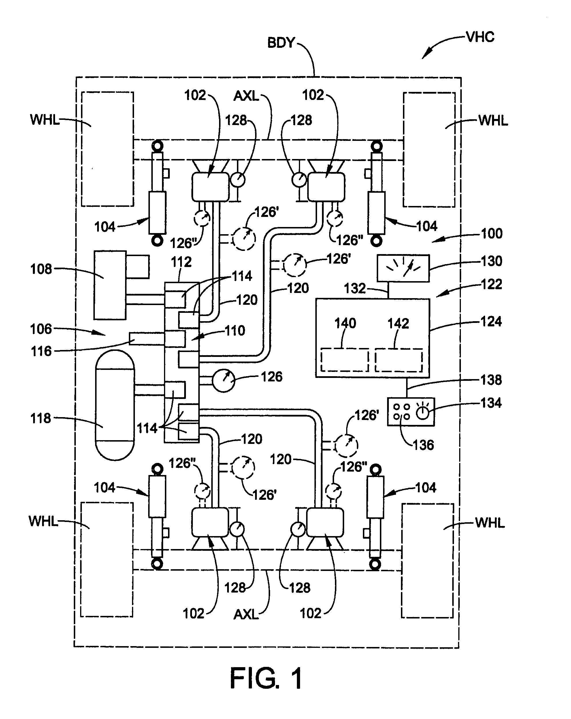
[0020]Turning now to the drawings wherein the showings are for the purpose of illustrating exemplary embodiments of the present novel concept and not for the purpose of limiting the same, FIG. 1 illustrates an embodiment of a suspension system 100 disposed in operative association between a sprung mass, such as an associated vehicle body BDY, for example, and an unsprung mass, such as an associated wheel WHL or an associated axle AXL, for example, of an associated vehicle VHC. Suspension system 100 includes at least one fluid spring device, such as a plurality of fluid or air spring assemblies 102, for example, and at least one variable-rate damping device, such as a plurality of dampers or damping members 104, for example. Preferably, dampers 104 are capable of having the damping rate thereof varied between two or more damping rates in response to a non-fluid communication, such as an analog or digital electrical signal, message or communication, for example. One example of a suita...


PUM


Abstract

A control system is operatively associated with a suspension system of a vehicle. The associated suspension system includes an associated fluid spring operating at an associated fluid pressure and an associated variable-rate damper having an associated electronically-variable damping rate. The control system includes a pressure sensor operative to generate a pressure sensor signal indicative of the associated fluid pressure of the associated fluid spring, and a controller in communication with the pressure sensor and the associated variable-rate damper. The controller is operative to receive the pressure sensor signal and generate a damper adjustment signal based at least partially on the pressure sensor signal for adjusting the associated electronically-variable damping rate of the associated variable-rate damper. A vehicle suspension system includes such a control system, and a method of controlling a suspension system of a vehicle is also included.

Description

BACKGROUND[0001]The present novel concept broadly relates to the art of vehicle suspension systems and, more particularly, to a vehicle suspension system utilizing electronically-variable damping based upon an air spring pressure, and a method of controlling a vehicle suspension using the same.[0002]The present novel concept finds particular application and use in conjunction with suspension systems of wheeled vehicles, and will be described herein with specific reference thereto. However, it is to be appreciated that the present novel concept is also amenable to use in other applications and environments, and that the specific uses shown and described herein are merely exemplary.[0003]It is well known that land vehicles of most types and kinds are outfitted with a suspension system that supports a sprung mass of the vehicle (e.g., a body or chassis) on an unsprung mass of the vehicle (e.g., an axle or wheel-engaging member). Known suspension systems typically include a plurality of...

Claims


Application Information

Patent Timeline
Patent Type & Authority Patents(United States)
IPC IPC(8): B60G17/016
CPCB60G17/08B60G2400/252B60G2600/70B60G2500/102B60G2400/51222
Inventor QUICK, CRAIG E.NORDMEYER, DANIEL L.
Owner DRIVERIGHT HLDG
Why Eureka
Try Eureka