
Microcantilevers for biological and chemical assays and methods of making and using thereof

a technology of microcantilevers and applied in the field of microcantilevers for biological and chemical assays, can solve the problems of affecting the accuracy of measurements, unwanted deflection, and low sensitivity of prior art, and achieve the effect of less subject to drag

Inactive Publication Date: 2007-10-30
RGT UNIV OF CALIFORNIA
View PDF1 Cites 22 Cited by
  • Summary
  • Abstract
  • Description
  • Claims
  • Application Information

AI Technical Summary

Benefits of technology

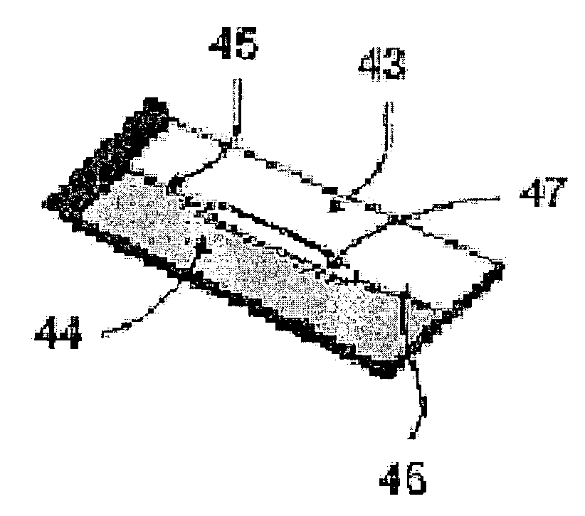
The present invention provides a microcantilever with a structural shape that allows for detectable characteristics when a ligand is complexed with a receptor immobilized on the microcantilever. The microcantilever has a longer extension length than an ordinary microcantilever, which provides better sensitivity and reduced drag. The microcantilever can also have a thermal capacitance that is larger than an ordinary microcantilever, which makes it more suitable for thermal analysis. The microcantilever can have a C-shaped or L-shaped structure, with the first section attached to a solid support and the second section attached at a right angle to the first section. The microcantilever can also have a detectable characteristic based on the deflection of the ends of the microcantilever.

Problems solved by technology

Unfortunately, microcantilevers are subject to turbulence in the liquid flow of samples which affects the accuracy of the measurements.
Additionally, microcantilevers in the prior art have low sensitivity especially for low analyte concentration and variations in sample temperature can produce unwanted deflections due to bimaterial effects as discussed by Fritz, J. et al.
In a liquid environment, turbulence effects may result in additional three-dimensional deflections of the microcantilever beam which will render any detection measurements useless.
In addition, the presence of a focused laser beam in a liquid environment can result in additional thermal effects that can result in extraneous readings.

Method used


Image

  • Microcantilevers for biological and chemical assays and methods of making and using thereof
  • Microcantilevers for biological and chemical assays and methods of making and using thereof
  • Microcantilevers for biological and chemical assays and methods of making and using thereof

Examples


Embodiment Construction

[0085]The present invention provides microcantilevers that may be used in methods and devices for detecting, measuring, monitoring, or analyzing low concentrations of at least one analyte in a fluid sample. In particular, the present invention provides microcantilevers upon which a specific binding agent may be immobilized for use in methods and devices for assaying ligand, present in a fluid sample, that specifically binds the specific binding agent.

[0086]As used herein, “assaying” is used interchangeably with “detecting”, “measuring”, “monitoring” and “analyzing”. As used herein, a “fluid sample” refers to a continuous amorphous substance that tends to flow and to conform to the outline of a container such as a liquid or a gas. Fluid samples include blood, plasma, urine, bile, breast milk, semen, water, liquid beverages, air, and the like. If one desires to test a solid sample for a given analyte according to the present invention, the solid sample may be made into a fluid sample ...


PUM

PropertyMeasurementUnit
distanceaaaaaaaaaa
distanceaaaaaaaaaa
distanceaaaaaaaaaa

Abstract

Disclosed herein are microcantilevers having structural shapes that are less sensitive to turbulence and drift effects yet provide greater deflections due to analyte concentration. The structural shapes include a C-shaped microcantilever, an E-shaped microcantilever, an L-shaped microcantilever, a double microcantilever, a slit microcantilever, a tapered microcantilever, and a triangular microcantilever. The microcantilevers may be piezoresistive microcantilevers. Also disclosed are microsensors, microfludic devices, and biochips that comprise the microcantilevers as well as methods of using the microcantilevers to detect analytes in a fluid sample.

Description

CROSS-REFERENCE TO RELATED APPLICATIONS[0001]This application claims the benefit of U.S. Provisional Patent Application No. 60 / 376,531 filed 29 Apr. 2002, which names Kambiz Vafai, Cengiz Ozkan, and Robert C. Haddon as inventors, U.S. Provisional Patent Application No. 60 / 411,354 filed 16 Sep. 2002, which names Kambiz Vafai, Cengiz Ozkan, Robert C. Haddon, Abdul-Rahim A. Khaled, and Mo Yang as inventors, and U.S. Provisional Patent Application No. 60 / 417,440 filed 9 Oct. 2002, which names Kambiz Vafai, Cengiz Ozkan, Robert C. Haddon, Abdul-Rahim A. Khaled, and Mo Yang as inventors, all of which are herein incorporated by reference in their entirety.BACKGROUND OF THE INVENTION[0002]1. Field of the Invention[0003]The present invention generally relates to microsensors for assaying analytes. In particular, the present invention relates to microcantilevers and methods of making and using thereof.[0004]2. Description of the Related Art[0005]The rapid growth of nanotechnology has led to n...

Claims


Application Information

Patent Timeline
Patent Type & Authority Patents(United States)
IPC IPC(8): C12M1/34
CPCG01N33/54373B82Y30/00
Inventor VAFAI, KAMBIZOZKAN, CENGIZHADDON, ROBERT C.KHALED, ABDUL-RAHIM A.YANG, MO
Owner RGT UNIV OF CALIFORNIA
Learn More