Gravitational electric power generating device

a gravity electric and power generation technology, applied in mechanical energy handling, mechanical equipment, machines/engines, etc., can solve the problems of high cost of hydroelectric power plant construction, environmental pollution, and generating capacity of the entire plant, and achieve the effect of optimal environmental protection benefits, low cost and high generating capacity

Inactive Publication Date: 2007-10-30
CHIANG CHIN HUI +1
View PDF10 Cites 11 Cited by
  • Summary
  • Abstract
  • Description
  • Claims
  • Application Information

AI Technical Summary

Benefits of technology

[0005]A primary objective of the present invention is to provide a gravitational electric power generating device making use of animals or moving objects, gravitational force, and lever principle to generate electricity, which has lower cost, higher generating capacity, and optimal environmental protection benefits.
[0006]To achieve the above-mentioned objective, a gravitational electric power generating device in accordance with the present invention includes at least a spinning wheel and two mount assemblies. Each of the spinning wheels has a first spoke rim, a second spoke rim, a wheel hub, and at least a tread-wheel. The first spoke rim and the second spoke rim are separately disposed at the outermost sides of the tread-wheel. The wheel hub is located between the first spoke rim and the second spoke rim and is disposed in the center of the two spoke rims. The wheel hub has a holding device and is wrapped on the driving shaft in a rotating manner. The two mount assemblies are erected at the two ends of the driving shaft, respectively, for supporting the driving shaft and the spinning wheel on the driving shaft. The holding device of the wheel hub can clamp the driving shaft. When the holding device is in an unclamping state, the spinning wheel can rotate around the driving shaft freely. When the holdi

Problems solved by technology

As is well-known, the cost of building a hydroelectric power plant is very high, and the environmental conditions/factors can affect the generating capacity of the entire plant.
The thermal electric power plant produces exhaust fumes in combustion and results in environmental pollution, which is an extremely severe problem.
In addition, the thermal electric power plant also has high construction costs.
For the wind power generation option, the cost is lower but the environmental factors can affect it and the generating capacity is limited.
The cost for the solar energy electricity generation is lower and the corresponding met

Method used


Image

  • Gravitational electric power generating device
  • Gravitational electric power generating device
  • Gravitational electric power generating device

Examples


Embodiment Construction

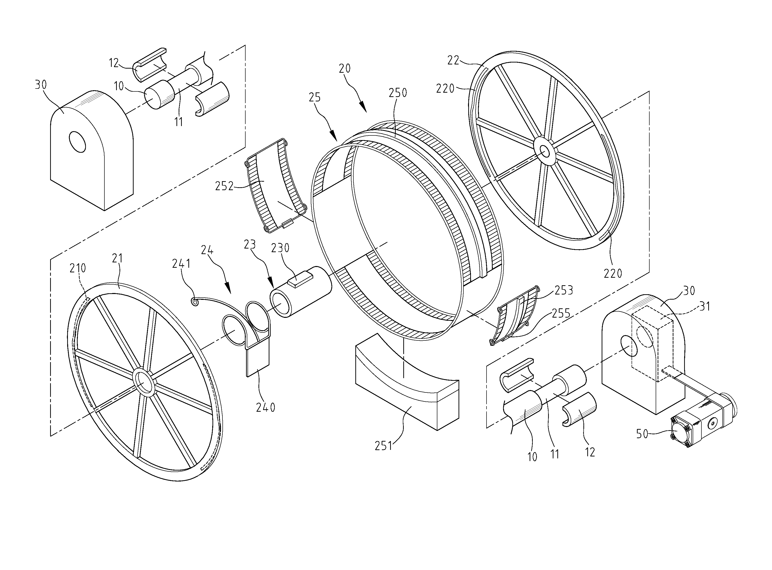
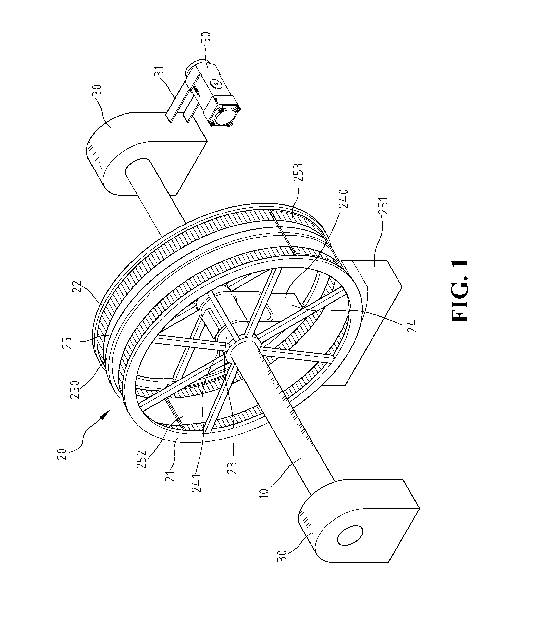
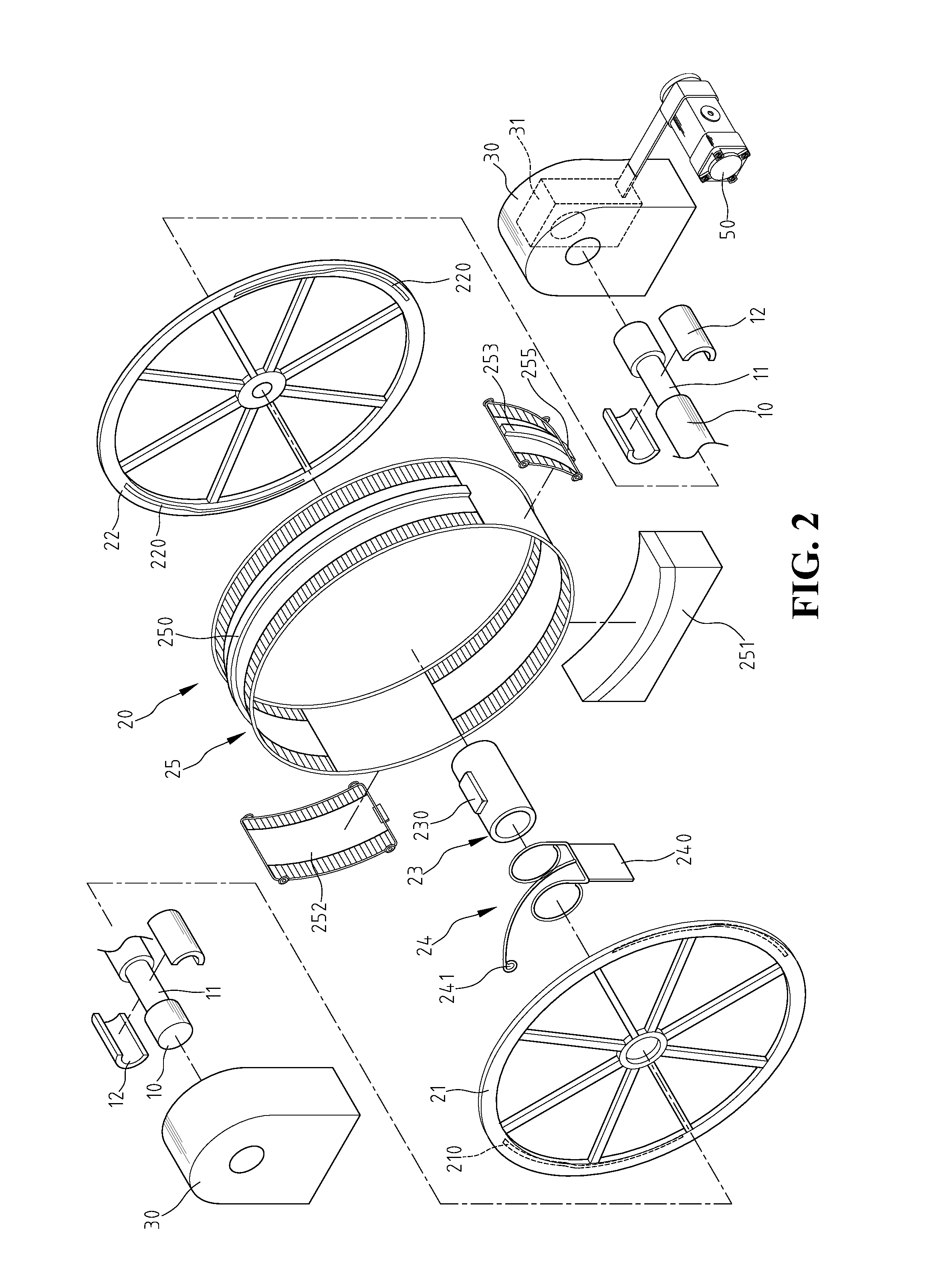
[0019]FIG. 1 is a perspective view of a gravitational electric power generating device according to a first preferred embodiment of the present invention. FIG. 2 is an exploded perspective view of the gravitational electric power generating device, according to the first preferred embodiment of the present invention. As illustrated in the above figures in the first embodiment of the present invention, the gravitational electric power generating device includes a driving shaft 10, a spinning wheel 20, and two mount assemblies 30. On the two ends of the driving shaft 10, there are a plurality of grooves 11 and magnets 12 in the grooves 11. The spinning wheel 20 has a first spoke rim 21, a second spoke rim 22, a wheel hub 23, and a tread-wheel 25. The first spoke rim 21 and the second spoke rim 22 are disposed at the two sides of the tread-wheel 25 individually, and have a plurality of snap-fit tracks 210, 220 on the inner sides of the spoke rims 21, 22. The front draw-gate 252 and the...


PUM


Abstract

A gravitational electric power generating device includes a driving shaft, at least a spinning wheel, and two mount assemblies, in which each of the spinning wheels includes a first spoke rim, a second spoke rim, a wheel hub, and at least a tread-wheel. The two mount assemblies are erected at the two ends of the driving shaft, respectively, and can support both the driving shaft and the spinning wheel on the driving shaft. Using a moving object to move in the tread-wheel, and making use of the gravitational effect of the moving object, the spinning wheel is able to drive the driving shaft to rotate. The mount assemblies have a power conversion module, which is connected to an electric generator. The rotational inertia of the driving shaft is transmitted to the electric generator to generate the electric power using the power conversion module.

Description

BACKGROUND OF THE INVENTION[0001]1. Field of the Invention[0002]The present invention relates to a gravitational electric power generating device, and especially to an electric power generating device making use of animals or moving objects, gravitational force, and lever principle to generate electricity, which has lower cost, higher generating capacity and optimal environmental protection benefits.[0003]2. The Prior Arts[0004]The conventional electricity generation methods mostly are, for example, hydraulic power generation, thermal power generation, wind power generation, solar energy electricity generation, or nuclear power electricity generation. As is well-known, the cost of building a hydroelectric power plant is very high, and the environmental conditions / factors can affect the generating capacity of the entire plant. The thermal electric power plant produces exhaust fumes in combustion and results in environmental pollution, which is an extremely severe problem. In addition...

Claims


Application Information

Patent Timeline
IPC IPC(8): F03G5/02
CPCF03G5/025
Inventor CHIANG, CHIN-HUICHIANG, HSIN-JUNG
Owner CHIANG CHIN HUI
Why Eureka
Try Eureka