Optical system including an anamorphic lens

an optical system and anamorphic technology, applied in the field of optical systems including anamorphic lenses, can solve the problems of difficult conversion between various formats of existing projectors, problems such as recording devices, and heavy weight, and achieve the effect of high flexibility and easy insertion or removal

Active Publication Date: 2007-10-30
RAYTHEON CANADA LTD
View PDF18 Cites 25 Cited by
  • Summary
  • Abstract
  • Description
  • Claims
  • Application Information

AI Technical Summary

Benefits of technology

[0008]The present invention provides an optical system that is suitable for recording or projecting anamorphic images. The anamorphic optical system is more compact and lighter than conventional anamorphic optical systems, so that the optical system support may be smaller and lighter than with prior approaches. In some embodiments, the optical system may be readily converted between different anamorphic ratios, or between anamorphic and non-anamorphic imaging, so that a single camera or projector may be used in a wide range of imaging applications.
[0010]The positioning of the anamorphic lens group between the front lens group and the rear lens group of the primary lens group allows the anamorphic lens or lenses to be smaller and lighter in weight than the prior approach wherein the anamorphic lenses are mounted forward of the objective lens. Because the movable elements lie internally, between the front lens group and the rear lens group, the length of the optical system does not increase greatly, nor does the diameter of the optical system. The support structure of the optical system is not extended beyond the front lens group, as is required for conventional cantilevered optical anamorphic additions. Consequently, the support structure may be smaller and lighter than would otherwise be the case. There is a better balance of the weight of the optical components, which also reduces the weight of the support structure.
[0012]Various mechanical mount arrangements of the removable lens groups may be employed. For example, the anamorphic lens group and the secondary lens group may be configured as cartridges to be inserted into and removed from the central beam path. There may instead be a lens-group mount upon which the anamorphic lens group and the secondary lens group (and possibly additional lens groups) are mounted, and which accomplishes controllable insertion into the central beam path and removal from the central beam path of the anamorphic lens group and the secondary lens group. The lens-group mount may be a tumbler lens-group mount with the tumbler axis either perpendicular to or parallel to the central beam path, a carousel lens-group mount, a transverse slider, a two-position zoom slider, or any other operable type. The placement of the removable / insertable lens groups between the front lens group and the rear lens group of the primary lens group allows such a cartridge or lens-group mount to be made smaller and lighter than if the removable / insertable lens groups were mounted in front of the primary lens group.
[0013]The present approach allows the optical system of a camera or projector to be highly flexible by permitting convenient conversion between different aspect ratios or other lens features. The placement of the anamorphic lens group and the secondary lens group between the lenses of the primary lens group allows the lenses of the anamorphic lens group and the secondary lens group to be smaller and lighter than would otherwise be the case, which in turn allows them to be mounted for easy insertion or removal.

Problems solved by technology

Accordingly, the anamorphic lens structures must be large in diameter, and are consequently heavy and cumbersome.
Existing projectors are difficult to convert between these various formats, at least partially because of the anamorphic lens structure.
These same problems may arise for recording devices, particularly digital recording cameras, that receive and record an image.

Method used


Image

  • Optical system including an anamorphic lens
  • Optical system including an anamorphic lens
  • Optical system including an anamorphic lens

Examples


Embodiment Construction

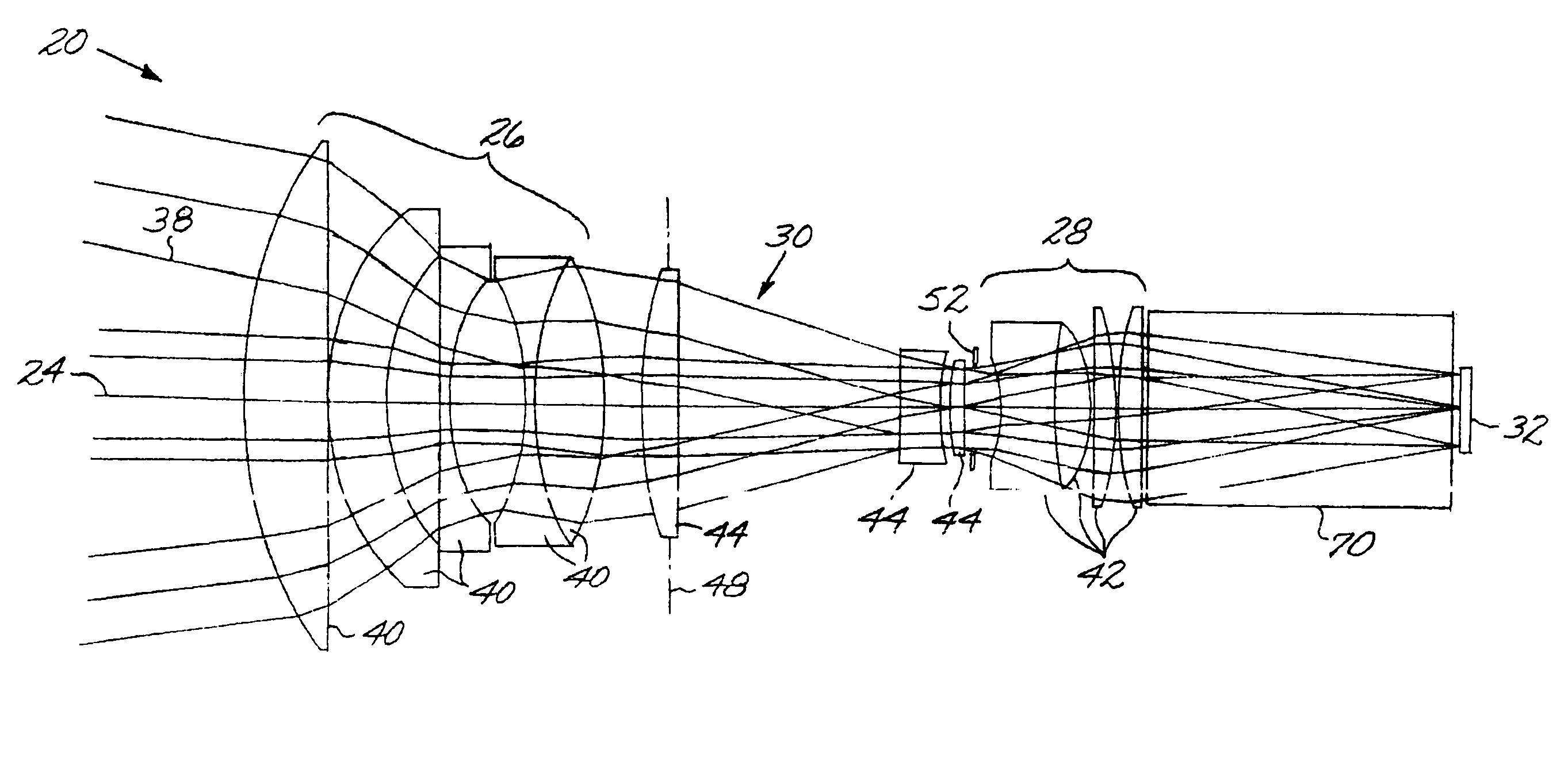
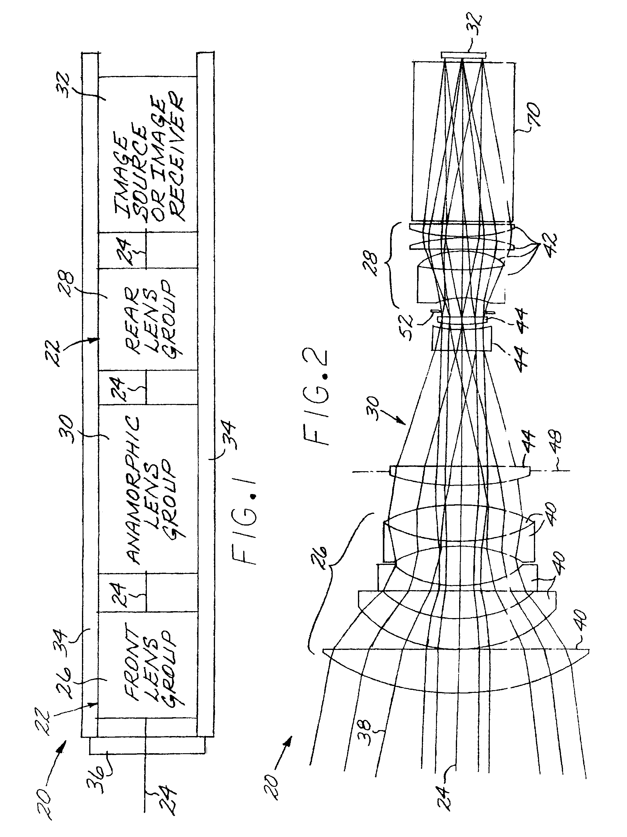
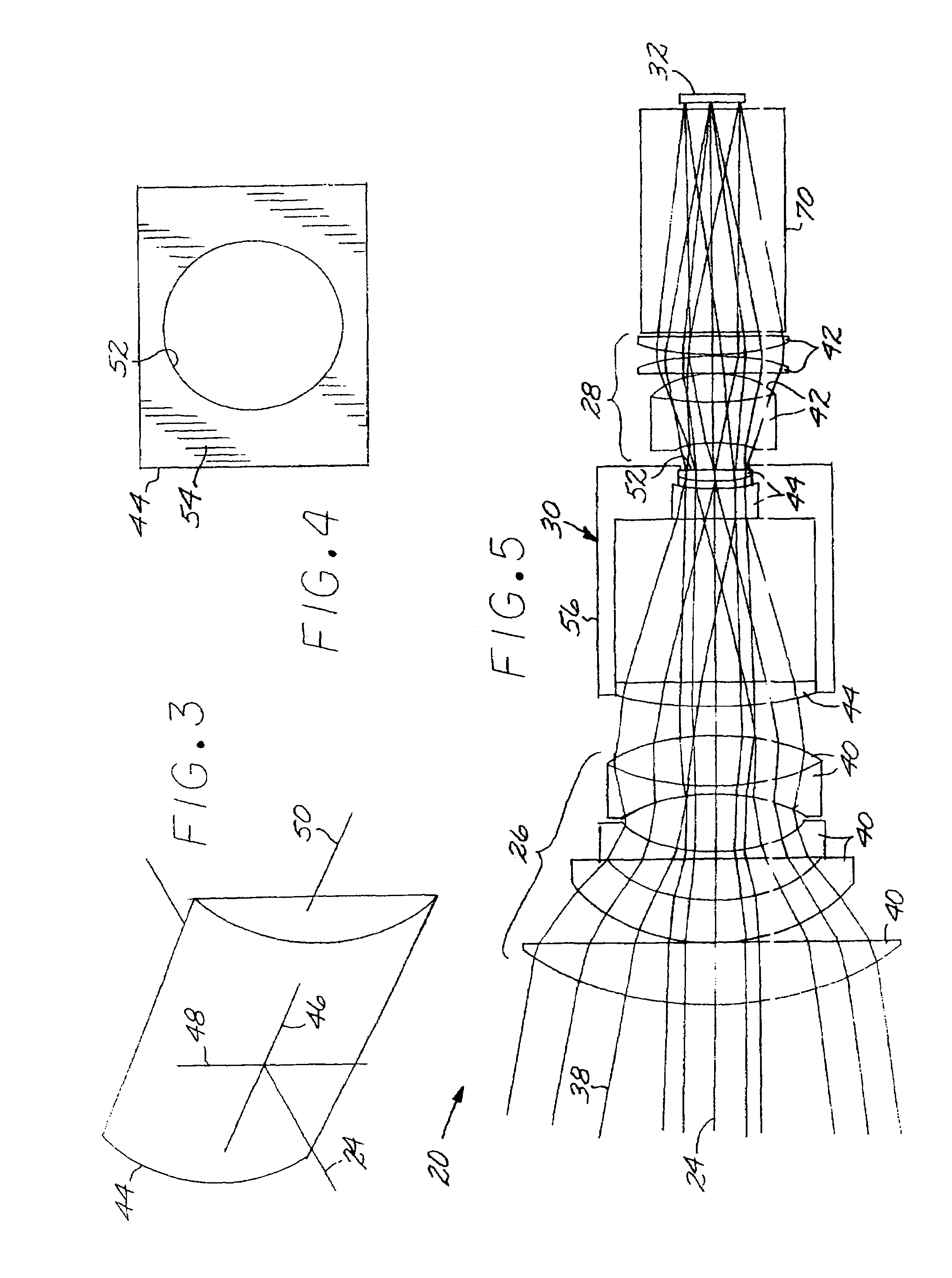
[0025]FIG. 1 depicts in block-diagram form an optical system 20 having a primary lens group 22 with a central beam path 24 therethrough. The primary lens group 22 includes a front lens group 26 and a rear lens group 28. An anamorphic lens group 30 lies on the central beam path 24 between the front lens group 26 and the rear lens group 28. The anamorphic lens group 30 may not be placed to the left (in the view of FIG. 1) of the front lens group 26 or to the right (in the view of FIG. 1) of the rear lens group 28. There is an image transceiver 32 that may be either an image source or an image receiver. The present approach may be used with visible or non-visible light such as infrared light, with the proper choice of optical components.

[0026]If the image transceiver 32 is an image source, the optical system 20 is a projector, and light travels (from right to left in the view of FIG. 1) on the central beam path 24 successively from the image source 32, through the rear lens group 28, t...


PUM


Abstract

An optical system includes a primary lens group having a central beam path therethrough and including a front lens group and a rear lens group. An anamorphic lens group lies on the central beam path and is positioned between the front lens group and the rear lens group. The anamorphic lens group includes at least one optically powered anamorphic lens that has different enlargements of a light beam along different axes perpendicular to the central beam path. The anamorphic lens group may be mounted on structure that allows it to be removed from the central beam path. An image transceiver is either an image source that directs a light beam through the primary lens group and the anamorphic lens group, or is an image receiver that receives a light beam through the primary lens group and the anamorphic lens group.

Description

[0001]This invention relates to an optical system, and more particularly to an optical system that achieves anamorphic image formation.BACKGROUND OF THE INVENTION[0002]Theater (cinema) movies are projected in various aspect ratios, where the aspect ratio is defined as the ratio of the width to the height of the projected image as seen on the screen. The most common aspect ratios are the conventional 1.85:1 “flat” image and the 2.35:1 “scope” image. Historically, most televisions and computer displays have a 1.33:1 aspect ratio. High-definition television typically has a 1.78:1 aspect ratio, and many modern televisions are produced with this screen aspect ratio.[0003]Even though there are many aspect ratios in common use, and others may be introduced in the future, the images are typically recorded (i.e., stored) in a “native” format dictated by the physical dimensions of a film (if analog recording for analog playback) or a spatial light modulator (if digital recording for digital p...

Claims


Application Information

Patent Timeline
Patent Type & Authority Patents(United States)
IPC IPC(8): G02B13/08
CPCG02B13/12G02B13/08
Inventor BOWRON, JOHN W.JONAS, REGINALD PETER
Owner RAYTHEON CANADA LTD
Why Eureka
Try Eureka