
Controller area network (CAN) communication device

a communication device and control area technology, applied in the field of controller area network (can) communication devices, can solve the problems of shortening the number of suitable free codes during the advancement of development, coding system failure, code assignment failure,

Inactive Publication Date: 2007-10-30
MITSUBISHI ELECTRIC CORP
View PDF11 Cites 19 Cited by
  • Summary
  • Abstract
  • Description
  • Claims
  • Application Information

AI Technical Summary

Benefits of technology

[0024]The present invention is proposed to solve the problems described above. An object of the present invention is to realize a controller area network (CAN) communication device that enables IDs to be securely assigned without causing an ID coding system to fail and that enables communication to be securely guaranteed.

Problems solved by technology

However, according to the method of arbitrary assigning codes of IDs as shown in FIG. 9, although a sufficient number of free codes were available in an initial development stage, suitable free codes are running short during advancement of developments.
Thus, if a desired ID corresponding to the priority is not preserved free, the code assignment would fail.
However, it is obvious that the coding system would fail when functions are thus repeatedly added.
Thus, once an ID has been assigned, it is difficult to change the priority in order to maintain data compatible with another system.
In addition, in a network already in operation, a case can occur in which consecutive arbitration losses are caused while communication is carried out using a specific ID, establishing no proper communication.
Although this is avoidable with respect to a design, this leads to a problem, particularly, in the field of shipbuilding.
This makes it difficult for the engine manufacturer to control the system configuration.
Thus, the control of the system configuration is difficult for an engine manufacturer, particularly, in the field of shipbuilding.
This also makes it difficult for the manufacturer to estimate the total amount of traffic (communication amount).
Thus, depending on the system configuration, a traffic overflow may occur, resulting in causing communication failure.
Thus, filtering for all the IDs cannot be implemented using hardware.
Thus, the limitation is imposed on use of the hardware filtering functions of the CAN chip.
This arises a problem when a large number of IDs are to be transmitted.
Specifically, since all the large number of IDs must be checked, the software load is extremely increased.

Method used


Image

  • Controller area network (CAN) communication device
  • Controller area network (CAN) communication device
  • Controller area network (CAN) communication device

Examples


first embodiment

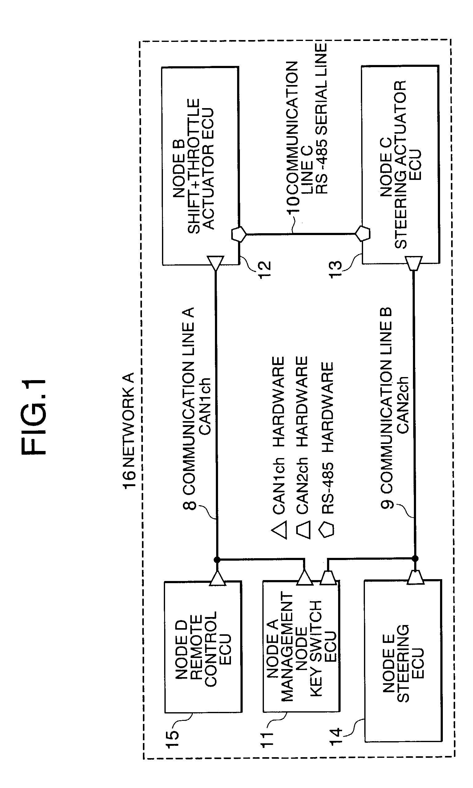
[0038]FIG. 1 shows a network configuration of a controller area network (CAN) communication device according to a first embodiment of the present invention. Hereinbelow, the configuration shown in FIG. 1 will be described.

[0039]Numeral 8 denotes a communication line A (CAN1ch), numeral 9 denotes a communication line B (CANa2ch), numeral 10 denotes a communication line C (RS-485 serial line), numeral 11 denotes a key switch engine control unit (ECU), numeral 12 denotes a shift+throttle actuator ECU, numeral 13 denotes a steering actuator ECU, numeral 14 denotes a steering ECU, numeral 15 denotes a remote control ECU, and numeral 16 denotes a network A (CAN communication device) configured to include all the aforementioned elements.

[0040]A plurality of nodes are connected to each of the communication lines 8 to 10. The network A16 includes the shift+throttle actuator ECU 12, the steering actuator ECU 13, the steering ECU 14, and the remote control ECU 15.

[0041]The key switch ECU 11 is...

second embodiment

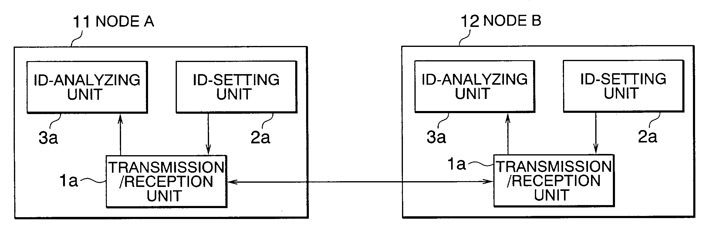
[0051]FIG. 5 shows intra-node configurations of a CAN communication device according to a second embodiment of the present invention. Each of the configurations is dissimilar to that of the first embodiment in that it includes a bit adjustment unit 4. The configurations of FIG. 5 are shown by way of example in which a node A of a key switch ECU 11 is connected to a node B of a shift+throttle actuator ECU 12.

[0052]Referring to FIG. 5, an ID-setting unit 2b in each of the nodes A and B sets a base priority indicating a priority that is transmitted in units of grouped predetermined function information to part of the bits of a CAN-ID field 6. Each of the nodes A and B includes the bit adjustment unit 4. The bit adjustment unit 4 reduces the value of the bits representing the base priority assigned to grouped predetermined function information in one of items of data to which base priorities are set by the ID-setting unit 2b, thereby adjusting the communication priority to be higher. A ...

third embodiment

[0061]FIG. 7 shows intra-node configurations of a CAN communication device according to a third embodiment of the present invention. Each of the configurations is dissimilar to that of the second embodiment in that the configuration includes an inter-gateway communication unit 3c. The configurations shown in FIG. 7 are shown by way of example in which a node A of a key switch ECU 11 is connected to a node B of a shift+throttle actuator ECU 12.

[0062]Referring to FIG. 7, each of the nodes A and B is a gateway node including at least a gateway function, and the gateway node is configured to include the following described hereinbelow. An ID-setting unit 2c sets inter-gateway transfer permission information indicating possibility / impossibility of inter-gateway data transfer in units of grouped predetermined function information to part of the bits of a CAN-ID field 6. A transmission / reception unit 1c transmits and receives data containing the inter-gateway transfer permission informatio...


PUM


Abstract

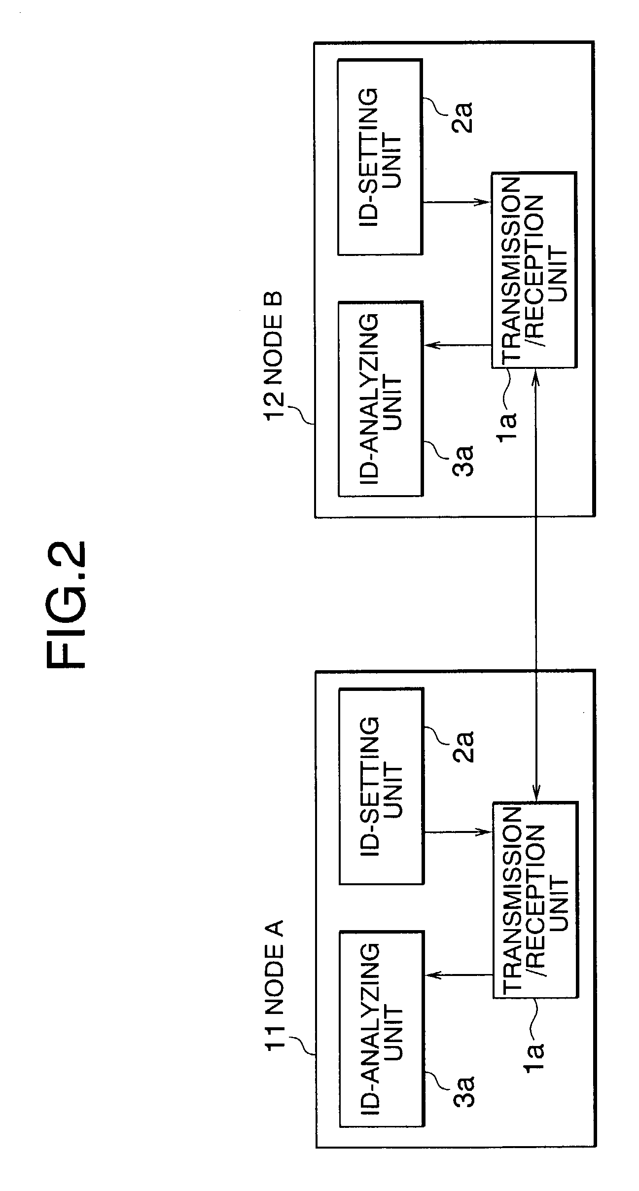
Provided is a control area network (CAN) communication device formed such that a plurality of nodes are connected to communication channels in the CAN. Each of the nodes includes a transmitting / receiving unit for transmitting and receiving data including a CAN-ID field formed of bits containing function information, an ID-setting unit for setting predetermined function information to the bits of the CAN-ID field contained in the data transmitted from the transmission / reception unit, and an ID-analyzing unit for analyzing the predetermined function information set in the CAN-ID field. The ID-setting unit groups the predetermined function information in units of a predetermined function, assigns a data-transmission priority, assigns a general function group ID, and assigns a communication category code ID used to identify a communication content to each item of the grouped predetermined function information to be set to part of the bits of the CAN-ID field.

Description

BACKGROUND OF THE INVENTION[0001]1. Field of the Invention[0002]The present invention relates to a controller area network (CAN) communication device improved in efficiency.[0003]2. Description of the Related Art[0004]In the field oft for example, automobiles, which is amid technological trends toward increase in modularized devices, intelligent devices, and devices with reduced harnesses, industries have started rapidly employing device controls using serial communication schemes represented by, for example, a controller area network (CAN) communication scheme.[0005]In particular, in the field of automobiles, a device connected via communication lines and thereby controlled is substantially fixed at a development stage, and no case occurs in which the device connection is changed at least during the stages of production and postproduction.[0006]Thus, in the serial communication represented by the CAN communication mounted on an automobile, IDs individually indicating, for example, ...

Claims


Application Information

Patent Timeline
IPC IPC(8): G01R31/08B60R16/02H04L12/42H04J1/16H04L12/28H04L12/413H04L12/46
CPCH04L12/40163H04L12/413H04L12/4625H04L2012/40273H04L2012/40215
Inventor ITOI, MAKOTO
Owner MITSUBISHI ELECTRIC CORP
Learn More