
Apparatus and method for measuring speed of a moving object

a technology for moving objects and apparatus, applied in the field of apparatus and methods for measuring the speed of moving objects, can solve the problems of large error in the measurement of speed, large difference between measured speed and position and actual speed and position, and inability to accurately measure the speed

Active Publication Date: 2007-10-30
SAMSUNG ELECTRONICS CO LTD
View PDF23 Cites 49 Cited by
  • Summary
  • Abstract
  • Description
  • Claims
  • Application Information

AI Technical Summary

Benefits of technology

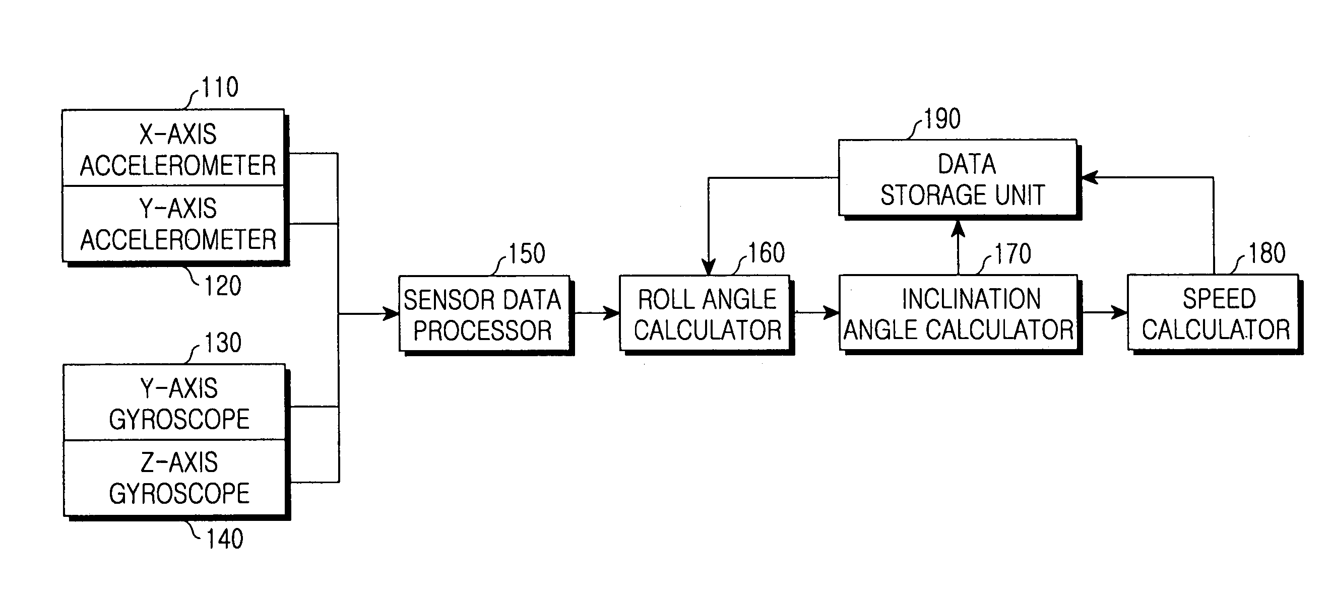
The present invention provides an apparatus and method for measuring the speed of a moving object based on roll movement. The apparatus includes accelerometers, gyroscopes, a roll angle calculator, an inclination angle calculator, and a speed calculator. The method involves measuring acceleration and angular speed, calculating the roll angle of the object using the acceleration and angular speed, calculating the road inclination angle using the roll angle and the angular speed, and calculating the pure motion acceleration of the object using the road inclination angle. The technical effects of this invention include improved accuracy and efficiency in measuring the speed of a moving object.

Problems solved by technology

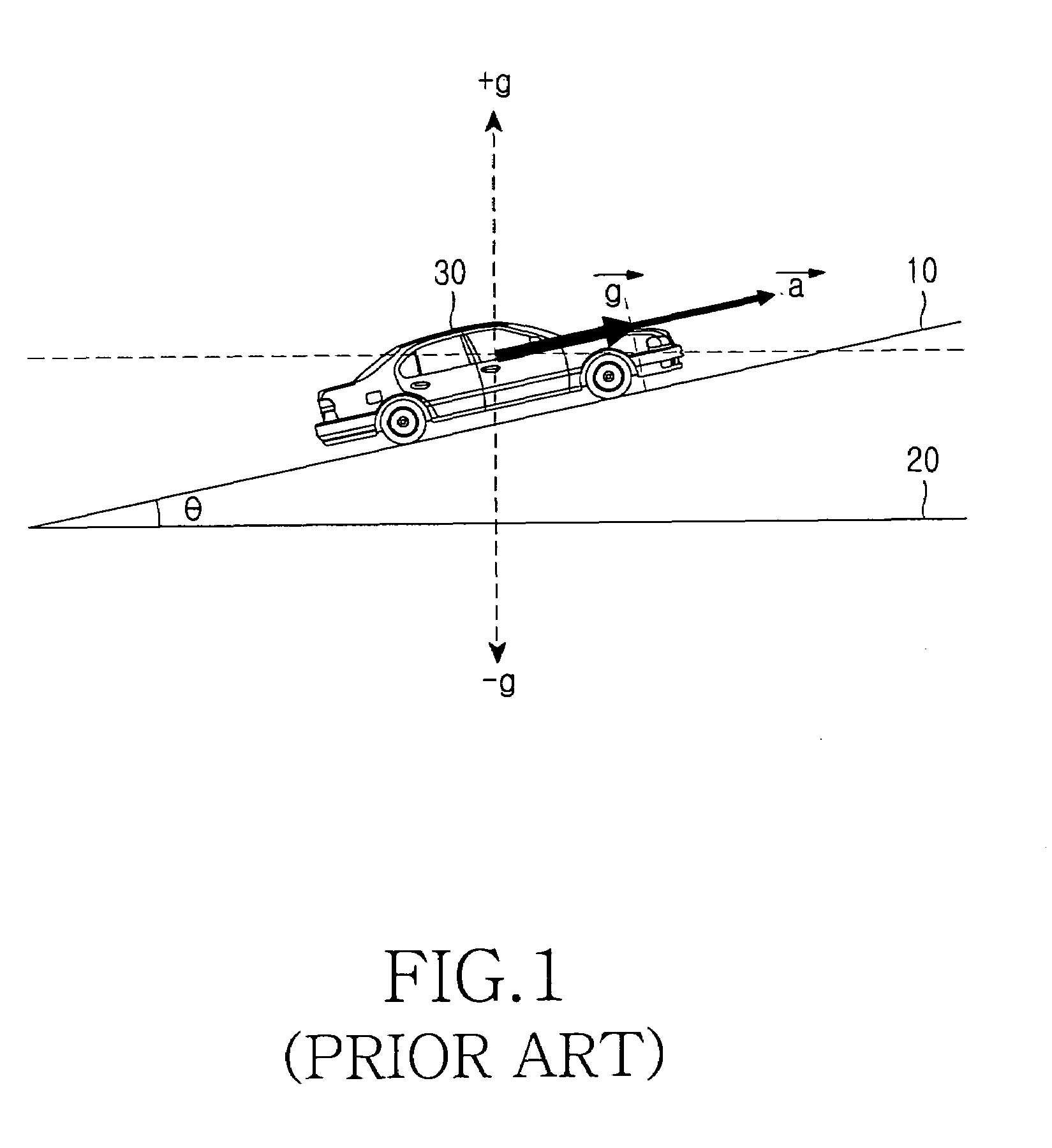
Thus, the component of the gravitational acceleration {right arrow over (g)} is also measured together with a rate of change in the actual speed of motion and may cause a big error in the measurement of speed.
As a result, a conventional calculation of the road inclination angle θ, which neglects the roll angle of the vehicle, has a significant error.
As a result, there are large differences between measured speed and position and actual speed and position.
However, to use the gyroscope for three axes, additional gyroscopes must be mounted in a DR system, increasing the manufacturing cost of the DR system for measuring the speed of the vehicle.

Method used


Image

  • Apparatus and method for measuring speed of a moving object
  • Apparatus and method for measuring speed of a moving object
  • Apparatus and method for measuring speed of a moving object

Examples


Embodiment Construction

[0045]A preferred embodiment of the present invention will now be described in detail with reference to the annexed drawings. In the following description, a detailed description of known functions and configurations incorporated herein has been omitted for conciseness.

[0046]An apparatus for measuring the speed of a moving object according to the present invention calculates the roll angle of the moving object using two axis gyroscopes and two axis accelerometers and measures the speed of the moving object based on the calculated roll angle.

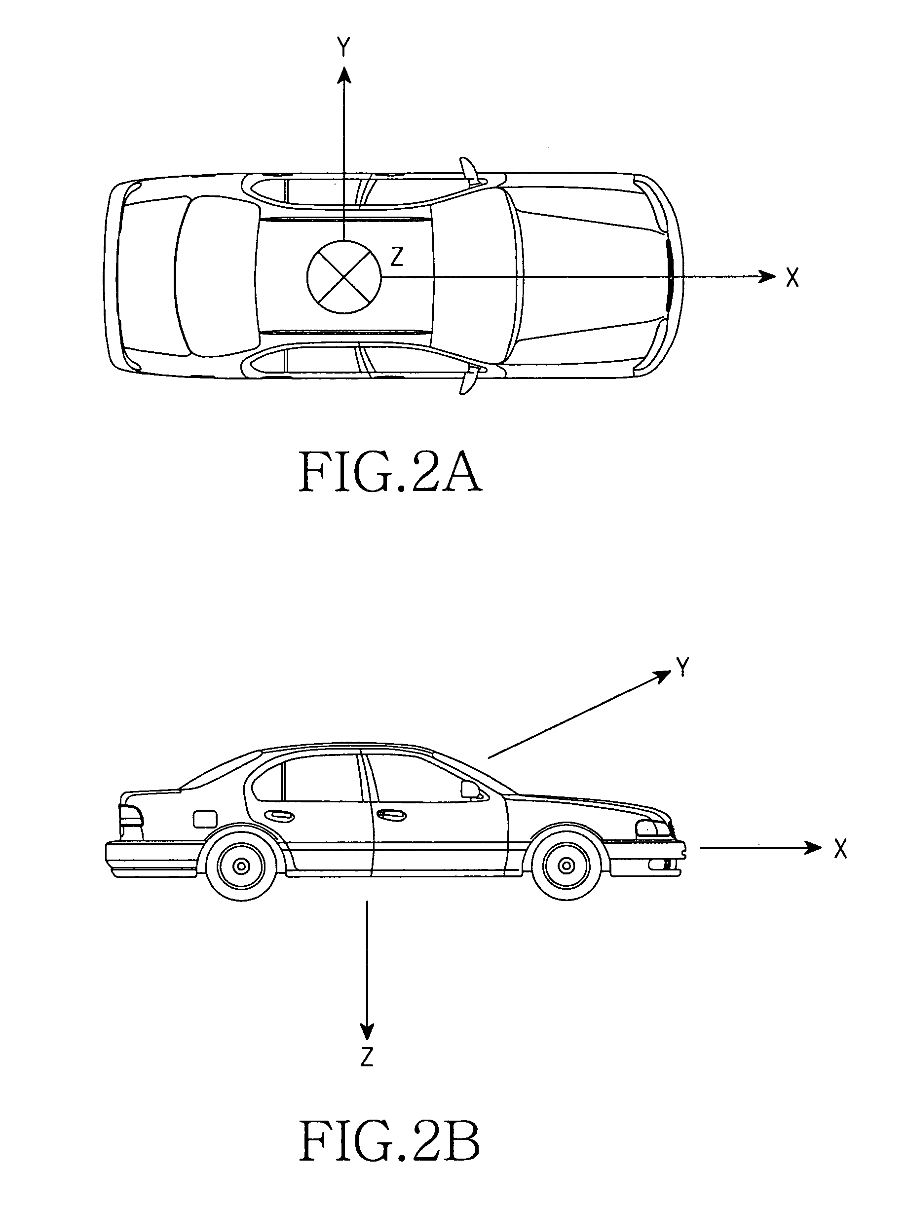
[0047]FIG. 3 is a view explaining an arrangement of a gyroscope and an accelerometer in a moving object according to the present invention. In FIG. 3, a moving object is a vehicle.

[0048]Referring to FIG. 3, an X axis is a wheel axis connecting the front and rear sides of the vehicle and is in parallel with the moving direction of the vehicle. A Y axis is perpendicular to the moving direction of the vehicle and passes through the lateral sides of ...


PUM


Abstract

An apparatus and method for measuring the speed of a moving object is provided. A first acceleration along the moving direction of the moving object and a second acceleration along the lateral direction of the moving object are measured. A first angular speed along the lateral direction of the moving object and a second angular speed along the lower direction of the moving object are measured. The roll angle of the moving object using the second acceleration, the second angular speed, and a previous speed of the moving object in the moving direction of the moving object, and a previous road inclination angle with respect to the moving direction of the moving object are calculated. A road inclination angle is calculated using the calculated roll angle, the first angular speed, and the second angular speed. A pure motion acceleration in the moving direction of the moving object is calculated using the calculated road inclination angle and the speed of the moving object is calculated using the pure motion acceleration of the moving object.

Description

PRIORITY[0001]This application claims priority under 35 U.S.C. § 119 to an application entitled “Apparatus and Method for Measuring Speed of Moving Object” filed in the Korean Intellectual Property Office on May 13, 2005 and assigned Serial No. 2005-40359, the contents of which are incorporated herein by reference.BACKGROUND OF THE INVENTION[0002]1. Field of the Invention[0003]The present invention generally relates to an apparatus and method for measuring the speed of a moving object, and in particular, to an apparatus and method for measuring the speed of these moving objects based on a roll angle.[0004]2. Description of the Related Art[0005]Generally, moving objects such as vehicles, ships, and aircrafts have an embedded navigation system that determines the position of the moving object (positioning), routes a path to a given destination (routing), and provides the routing results.[0006]In order to determine the position of a moving object and provide a path to the destination, ...

Claims


Application Information

Patent Timeline
Patent Type & Authority Patents(United States)
IPC IPC(8): B60T7/12G05D1/00G06F17/00G06F7/00G01C19/02
CPCG01C21/16G01P15/00G01P15/18G01P7/00B60W2520/16B60W2520/18G01C19/02
Inventor HONG, HYUN-SULEE, JAE-MYEON
Owner SAMSUNG ELECTRONICS CO LTD
Learn More