Vehicle front end structure
a front end and vehicle technology, applied in the direction of indirect heat exchangers, machines/engines, light and heating equipment, etc., can solve the problems of difficult effective cooling of auxiliary devices, and achieve the effect of reducing the center of gravity of the vehicle and reducing the damage to the front end panel
- Summary
- Abstract
- Description
- Claims
- Application Information
AI Technical Summary
Benefits of technology
Problems solved by technology
Method used
Image
Examples
first embodiment
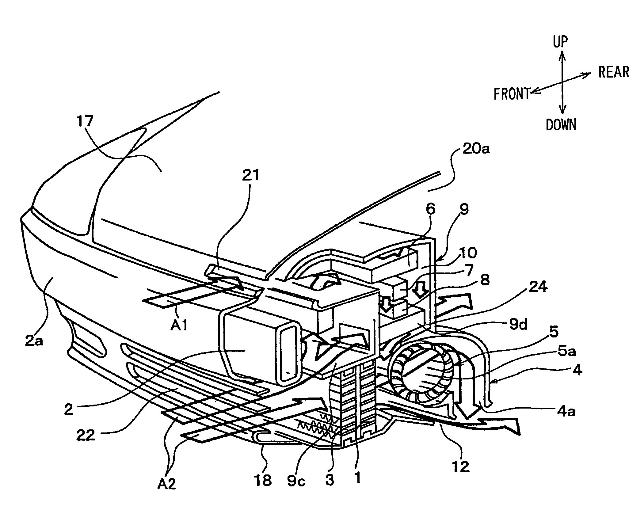
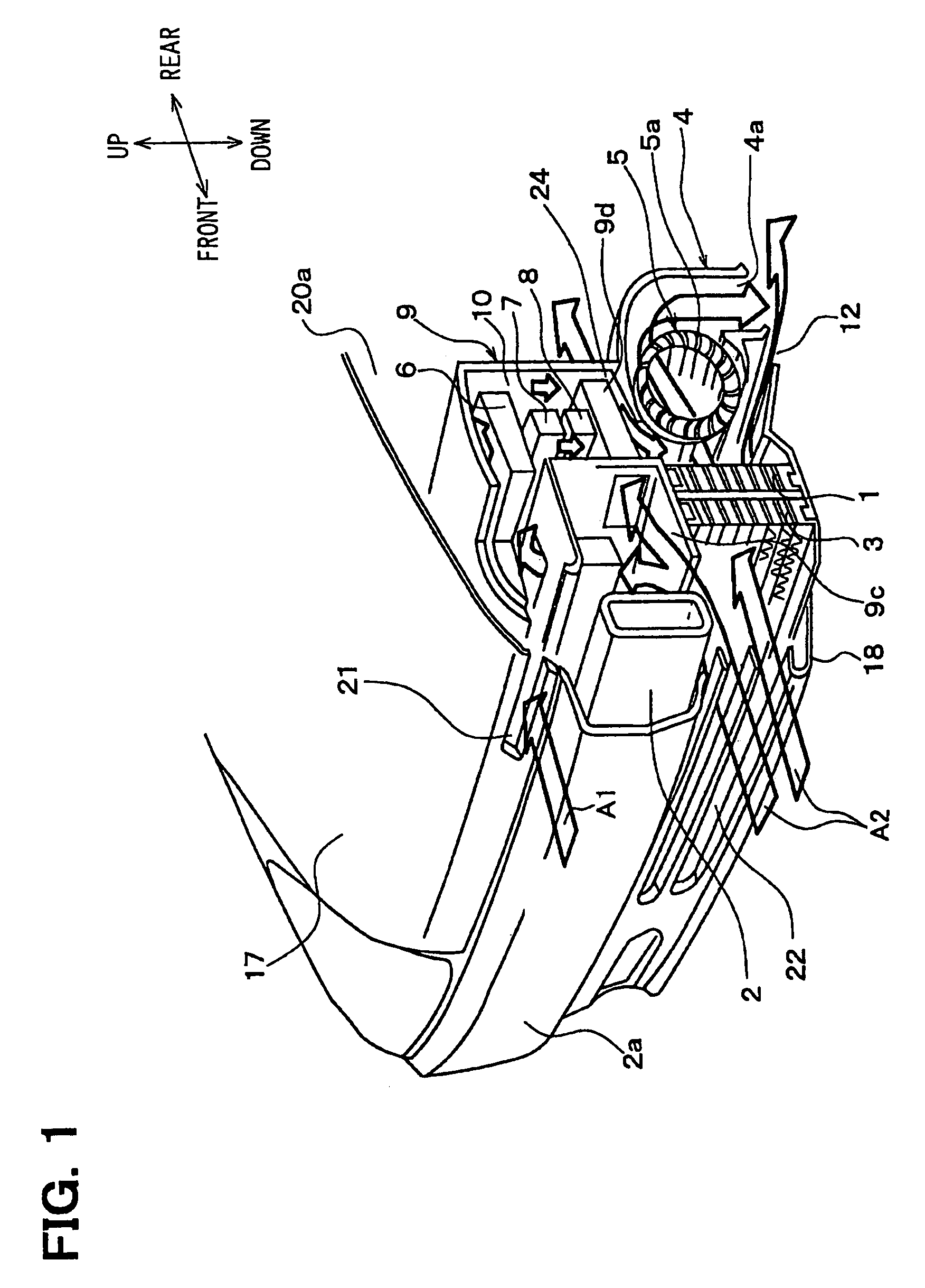
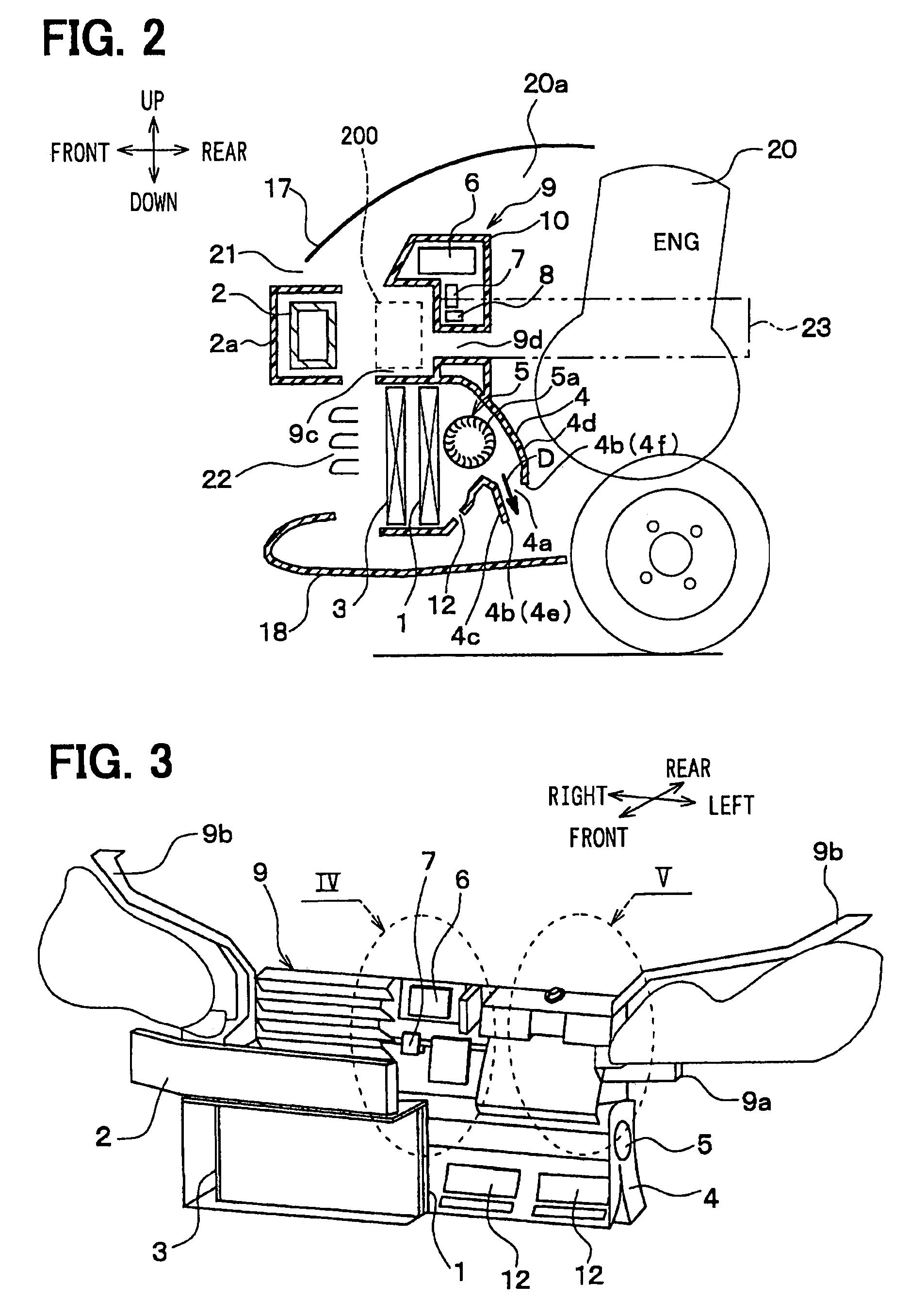
[0041]FIGS. 1 and 2 show a front end structure of a vehicle of the embodiment. FIG. 3 shows a schematic perspective view of a front end module in which a front end panel 9, heat exchangers 1, 3 for radiating heat and vehicle auxiliary devices are integrated, when viewed from a front side. In FIGS. 1 to 3, a front and rear arrow, an up and down arrow and a left and right arrow denote arrangement directions in the front end structure with respect to the vehicle.
[0042]Referring to FIGS. 1 to 5, the heat exchanger 1 is a radiator performing heat exchange between air (outside air) and an engine cooling water, thereby to cool the engine cooling water. The engine cooling water cools an engine (internal combustion engine) 20, which produces a driving power source of the vehicle.
[0043]In the embodiment, the radiator 1 has a width with respect to a vehicle left and right direction (width direction) larger than a height with respect to an up and down direction. That is, the radiator 1 is a fla...
second embodiment
[0087]In the second embodiment, an axial flow fan 5b is used in place of the transverse fan 5a of the first embodiment, as shown in FIG. 6. Also in this case, advantages similar to the first embodiment are provided.
third embodiment
[0088]In the first and second embodiments, the radiator 1 and the condenser 3 are arranged completely lower than the bumper reinforcement member 2. In the third embodiment, as shown in FIG. 7, the radiator 1 and the condenser 3 are arranged at a position lower than the top wall 2b of the bumper reinforcement member 2. Furthermore, the radiator 1 and the condenser 3 are inclined such that the top ends are located more to the rear side of the vehicle than the bottom ends, with respect to the vehicle front and rear direction. As shown in FIG. 7, core surfaces 1a, 3a of the radiator 1 and the condenser 3 define an angle of inclination θ1 with, respect to a vertical direction.
[0089]In the third embodiment, the upper portions of the radiator 1 and the condenser 3 are partly located behind the bumper reinforcement member 2. However, since the radiator 1 and the condenser 3 are arranged in the inclined position toward the rear side, the heat radiating performance of the radiator 1 and the c...
PUM
 Abstract
Description
Claims
Application Information
 - R&D
- Intellectual Property
- Life Sciences
- Materials
- Tech Scout
- Unparalleled Data Quality
- Higher Quality Content
- 60% Fewer Hallucinations
Browse by: Latest US Patents, China's latest patents, Technical Efficacy Thesaurus, Application Domain, Technology Topic, Popular Technical Reports.
© 2025 PatSnap. All rights reserved.Legal|Privacy policy|Modern Slavery Act Transparency Statement|Sitemap|About US| Contact US: help@patsnap.com


