Prismatic sealed battery

a sealed battery and prismatic technology, applied in the field of prismatic sealed batteries, can solve the problems of increasing heat generation, increasing cost, and increasing the complexity of the connection structure between the cells and the many component parts, and achieves the effects of reducing internal resistance, low connection resistance of prismatic batteries, and increasing power outpu

Inactive Publication Date: 2007-11-06
PANASONIC CORP +1
View PDF16 Cites 10 Cited by
  • Summary
  • Abstract
  • Description
  • Claims
  • Application Information

AI Technical Summary

Benefits of technology

[0025]According to this structure, as in the case described above, the current-carrying path between the electrode plate assembly and the collector is straight and short in each container, and the conductive connection member connects the collectors, opposed to each other across the partition between the containers, through the openings formed in the side wall of the prismatic battery case, so that it is possible to connect the collectors to each other at desired positions. Thus, as compared with a case that the collectors are connected at their upper end portions, since the current-carrying path does not detour and the connection path becomes short, the connection resistance of the prismatic battery becomes low. Also a plurality of connection paths even the distribution of current passing through the electrode plate assembly, so that internal resistance is reduced, and even and full use of the capability of the whole electrode plate assembly achieves higher power output. By sealing the container between the opening of the container on one side and the connection projection of the conductive connection member with reliability, electrolytic solution transfer is certainly prevented, and the seal member prevents the leak of electrolytic solution.
[0026]It is preferable that the opening leading into the container on at least one side takes the shape of a circle, and the connection projection of the conductive connection member takes the shape of a round shaft, and the sealing element disposed between the connection projection and the opening is an O-ring. By doing so, simply inserting the connection projection, on the outer periphery of which the O-ring is fitted, into the opening seals the container and to prevent electrolytic solution transfer, so that manufacturing efficiency is improved.
[0027]Furthermore, it is preferable that a plate for constituting the conductive connection member is press molded into the shape of a cylinder with a bottom to form the connection projection. By doing so, the conductive connection member having the connection projection is manufactured at low cost. Since a welding electrode inserted into the conductive connection member having the shape of a cylinder readily welds and connects its bottom face to another part such as the collector with high reliability, adverse effect on the sealing element during welding is prevented.
[0028]In the each structure described above, if connection terminals at both ends of the prismatic battery case are connected to the collectors, and collectors are connected to each other through connection holes formed in the upper portion of the partitions of the prismatic battery case, it is possible to use manufacturing equipment of conventional prismatic sealed batteries, in which the upper portions of the collectors are connected, as is, while the structure described above reduces connection resistance. Furthermore, since the connection terminals connected to the outside of the prismatic sealed battery are provided in the upper portions of both end walls of the prismatic battery case, it is easy to connect the prismatic sealed batteries to each other, and to secure electrical insulation when a cooling device using water or the like is provided.

Problems solved by technology

Increase in heat generation becomes barriers to the actualization of high power output and improvement in a lifetime.
Also there is a problem that the complex connection structure among the cells and the many component parts increase cost.
Thus, since current distribution passing through the electrode plate assembly 8 becomes uneven, the whole electrode plate assembly 8 does not evenly exercise its electric power generation capability, so that there is a problem that a large loss occurs.

Method used


Image

  • Prismatic sealed battery
  • Prismatic sealed battery
  • Prismatic sealed battery

Examples


first embodiment

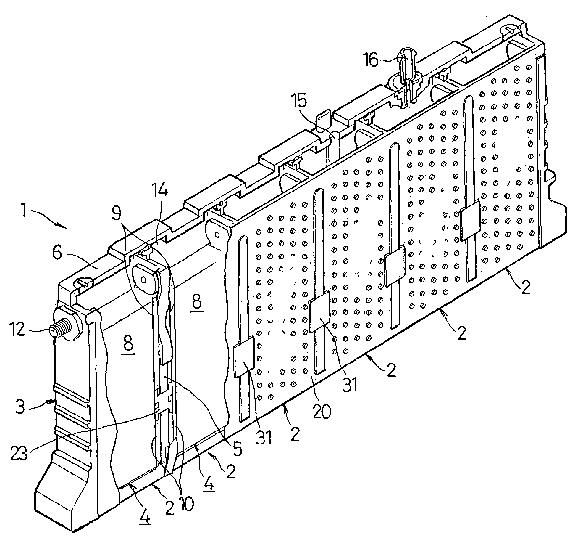
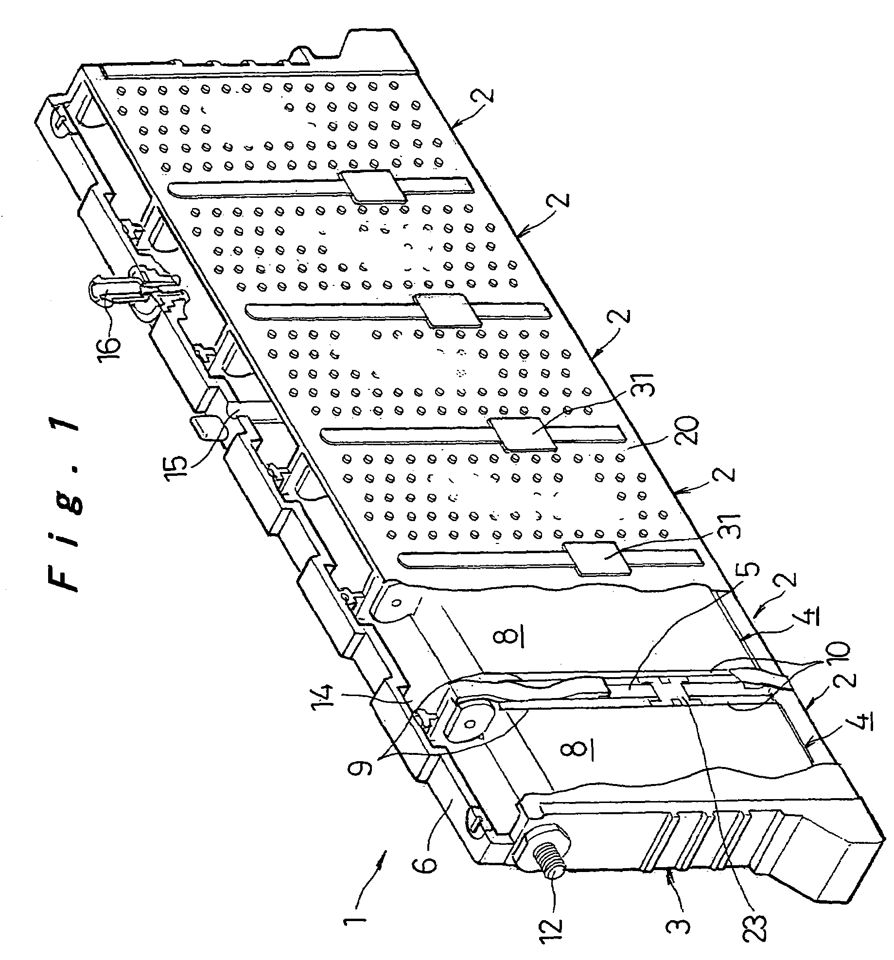
[0053]a prismatic sealed battery according to the present invention will be hereinafter described with reference to FIGS. 1 to 6. Elements identical to those of the conventional battery which has been described with reference to FIGS. 22 and 23 will be designated by the same reference numbers, and differences will be mainly described.

[0054]Referring to FIG. 1, a prismatic battery case 3 of a prismatic sealed battery 1 according to the present invention comprises a plurality of prismatic containers 4, having narrow-width sides and wide-width sides, which are integrally coupled to one another in a row so as to share the narrow-width sides as partitions 5. The prismatic battery case 3 is made of synthetic resin such as an alloy of PP and PPE having resistance to electrolytic solution or the like. Each container 4 contains an electrode plate assembly 8, both sides of which are connected to collectors 10 (10a and 10b), with electrolytic solution, to compose a cell 2. Connection holes 7 (...

second embodiment

[0066]the prismatic sealed battery according to the present invention will be hereinafter described with reference to FIGS. 7 to 9. In the following description of the embodiment, elements identical to those of the foregoing embodiment will be designated by the same reference numbers and the description thereof will be omitted, and only differences will be described.

[0067]In the foregoing embodiment, the opening 21 is sealed with resin by molding, after the conductive connection member 23 is welded. In this embodiment, the conductive connection member 23 is connected to the collectors 10, 10 by welding, and the resin layer 26 is hermetically joined to the partition 5 of the prismatic battery case 3 and the opening edge of the opening 21. Then, after a closing member 32 seals the opening 21 formed in the side wall 20 of the prismatic battery case 3, the closing member 32 is hermetically joined to the outer surface of the resin layer 26.

[0068]To be more specific, the opening 21 is rec...

third embodiment

[0071]Then, the prismatic sealed battery according to the present invention will be hereinafter described with reference to FIGS. 10 and 11.

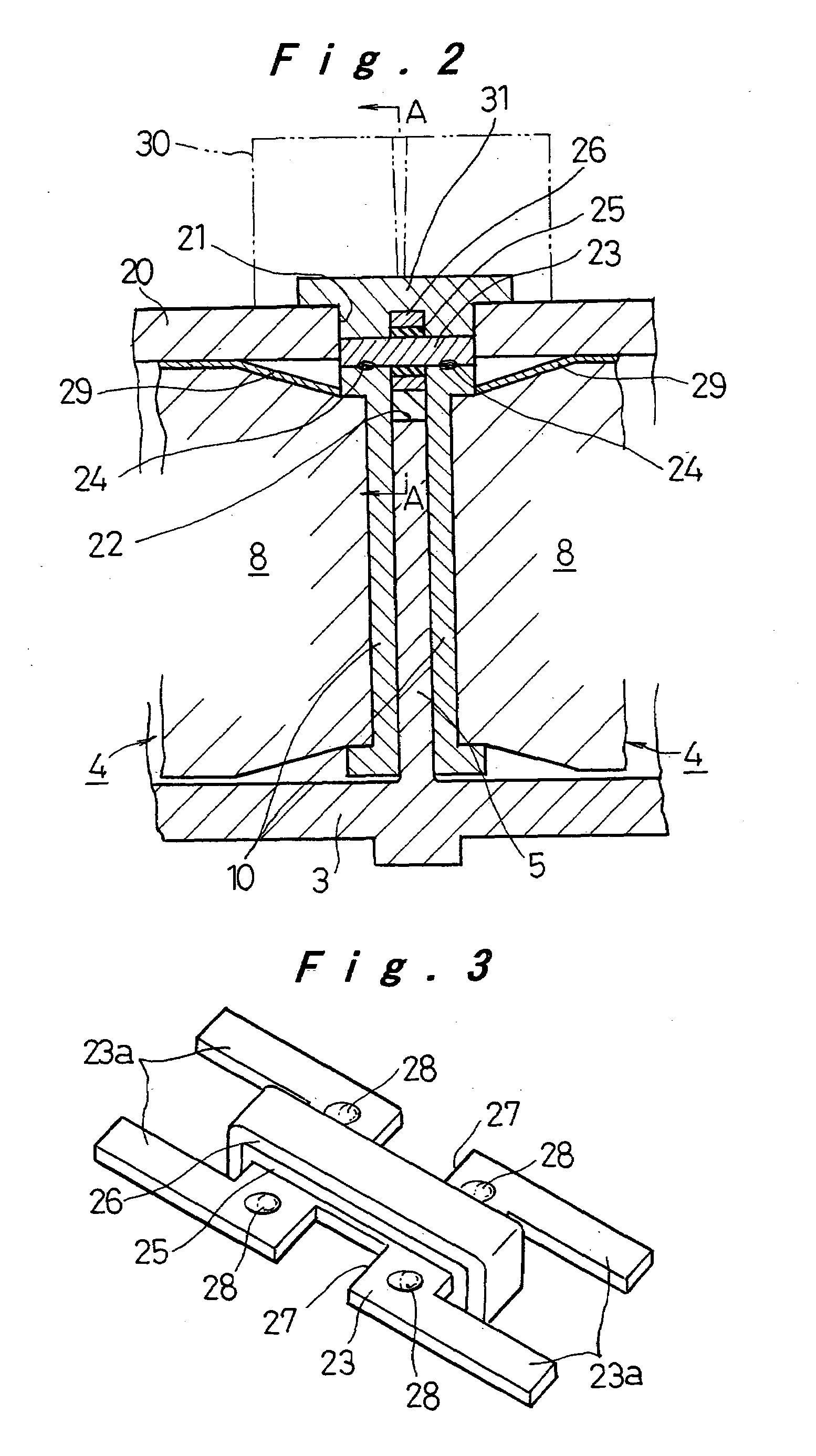
[0072]In the foregoing embodiments, the elastic body layer 25 is secured to the outer periphery of the middle of the conductive connection member 23 in the widthwise direction by baking, and the ring-shaped resin layer 26 made of the synthetic resin similar to that of the prismatic battery case 3 is provided around the periphery thereof. In this embodiment, a baked resin layer 36, which is made of synthetic resin having an affinity to the composition material of the prismatic battery case 3, is provided on the outer periphery of the middle of the conductive connection member 23 in the widthwise direction by baking. To form the baked resin layer 36, it is preferable that fine particles of synthetic resin, the melting point of which is lower than the injection molding temperature of the synthetic resin of the prismatic battery case 3, are stuck on...


PUM

PropertyMeasurementUnit
conductiveaaaaaaaaaa
elasticaaaaaaaaaa
affinityaaaaaaaaaa

Abstract

A prismatic sealed battery has a prismatic battery case (3) which includes a plurality of prismatic containers (4) coupled in a row via partitions (5), electrode plate assemblies (8), and collectors (10) which are joined to lead portions on both sides of the electrode plate assemblies (8). Each container (4) contains the electrode plate assembly (8) to which said collectors 10 are joined. An opening (21) is formed in at least one side wall (20) of the prismatic battery case (3) and in a position where each partition (5) is disposed, in such a manner as to face the containers (4) on both sides, and a conductive connection member (23) disposed in the opening (21) is connected to the collectors (10, 10) on both sides of the partition (5). Since the current-carrying path between the electrode plate assemblies (8) becomes short, internal resistance decreases, and hence internal resistance per cell (2) is reduced. Even and full use of the whole electrode plate assembly (8) achieves higher power output.

Description

TECHNICAL FIELD[0001]The present invention relates to a prismatic sealed battery, and more particularly to a prismatic sealed battery such as a battery module, including a plurality of connected cells, in which internal resistance is reduced.BACKGROUND ART[0002]A conventional battery module, including a plurality of connected individual cells to obtain predetermined capacity, includes a plurality of prismatic cells which are so disposed that the wide-width sides of containers thereof are opposed to each other, end plates attached to the outside of the containers of both end cells, a restraining band for integrally binding the cells and the end plates. In each cell, leads upwardly drawn out of the upper end portions of electrode plates are connected to terminals attached to a lid of the container, and connection plates connect the terminals of every cell to constitute the battery module.[0003]In the conventional battery module, the resistance of component parts including connection p...

Claims


Application Information

Patent Timeline
Patent Type & Authority Patents(United States)
IPC IPC(8): H01M2/24H01M2/04H01M2/08H01M2/26H01M6/46H01M6/42H01M50/112H01M50/176H01M50/529H01M50/534H01M50/548H01M50/553
CPCH01M2/021H01M2/0242H01M2/24H01M2/266H01M2/06H01M2/0217H01M6/42H01M50/103H01M50/112H01M50/529H01M50/534H01M50/553H01M50/176H01M50/548H01M50/531
Inventor KAJIYA, HIROMIKARASAWA, SHOJIONISHI, MASATOASAHINA, TAKASHIHAMADA, SHINJIETO, TOYOHIKO
Owner PANASONIC CORP
Why Eureka
Try Eureka