Comparator circuit with Schmitt trigger hysteresis character

a comparator circuit and trigger hysteresis technology, applied in the field of comparator circuits, can solve problems such as schmitt trigger hysteresis characters

Inactive Publication Date: 2007-11-06
ETRON TECH INC
View PDF14 Cites 21 Cited by
  • Summary
  • Abstract
  • Description
  • Claims
  • Application Information

AI Technical Summary

Benefits of technology

[0012]The objects of this invention are achieved by a differential comparator circuit with hysteresis. This circuit contains a current source which controls the magnitude of current flow through this comparator circuit. The circuit also has a first logic device which is turned ON by a reference voltage, and which when ON feeds current to the current source. A second logic device is turned ON by a comparator input voltage, and which when ON allows current to flow to the current source. A first feedback device is turned ON by a negative comparator output. A first parallel resistor is connected in parallel to the first feedback device. A second feedback device is turned ON by a positive comparator output. A second parallel resistor is connected in parallel to the second feedback device. A first load device is connected to the first feedback device. A second load device is connected to the second feedback device. The first and second parallel resistors are used to provide the differential comparator with switching voltage offsets which result in the Schmitt trigger hysteresis character.

Problems solved by technology

The first and second parallel resistors are used to provide the differential comparator with switching voltage offsets which result in the Schmitt trigger hysteresis character.

Method used


Image

  • Comparator circuit with Schmitt trigger hysteresis character
  • Comparator circuit with Schmitt trigger hysteresis character
  • Comparator circuit with Schmitt trigger hysteresis character

Examples


Embodiment Construction

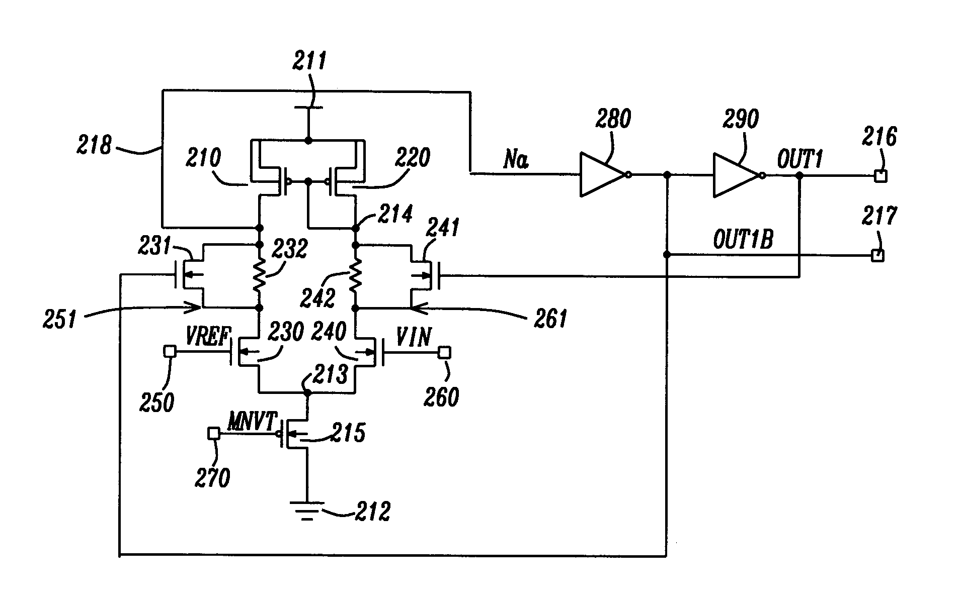
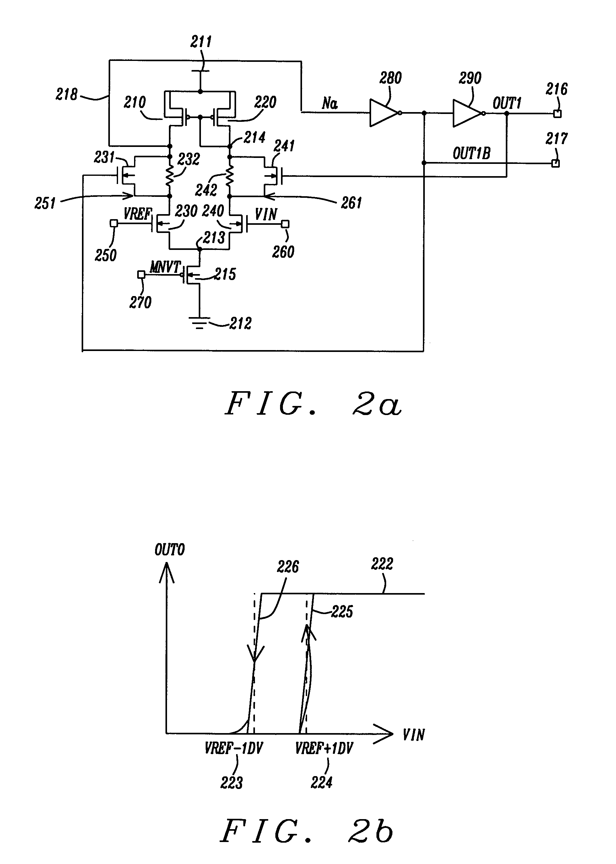
[0022]FIG. 2a shows the main embodiment of the comparator circuit of this invention. It is a differential comparator with hysteresis. Devices 210 and 220 are p-channel metal oxide semi-conductor field effect transistors (PMOS FETs). They are load devices with their sources and substrates connected to the power supply mode 211. The gates of devices 210 and 220 are connected in common to the drain 214 of device 220. The drain 218 of device 210 drives inverter 280. The output of inverter 280 is node OUT 1B (217). The output of inverter 280 feeds inverter 290, whose output is OUT1 (216). N-channel metal oxide semi conductor field effect transistors (NMOS FETs) 230 and 240 are the logic devices for the differential amplifier. The gate of device 230 is connected to a reference voltage, VREF, 250. The drain of device 230 is connected to node 251. The gate of 240 is connected to an input voltage, VIN 260. The drain of device 240 is connected to node 261. The sources of devices 230 and 240 a...


PUM


Abstract

A circuit and a method are provided to produce a novel comparator with Schmitt trigger hysteresis character. The circuit includes a current source which controls the magnitude of current flow through this comparator circuit. It has a first logic device which is turned ON by a reference voltage, and a second logic device is turned ON by a comparator input voltage. A first feedback device is turned ON by a negative comparator output. A first parallel resistor is connected in parallel to the first feedback device. A second feedback device is turned ON by a positive comparator output. A second parallel resistor is connected in parallel to the second feedback device. The first and second parallel resistors are used to provide the differential comparator with switching voltage offsets which result in the Schmitt trigger hysteresis character.

Description

BACKGROUND OF THE INVENTION[0001]1. Field of the Invention[0002]The present invention generally relates to comparator circuits. More particularly, this invention relates to a circuit and a method for differential comparators with hysteresis.[0003]2. Description of the Prior Art[0004]FIG. 1 shows a prior art comparator circuit without hysteresis. It is a simple operational amplifier (op amp). The figure shows a differential comparator circuit. Devices 110 and 120 are p-channel metal oxide semiconductor field effect transistors (PMOS FETs). They are load devices with their sources and substrates connected to the power supply node 111. The gates of devices 110 and 120 are connected in common to the rain 114 of device 120. The drain 118 of device 110 drives inverter 180. The output of inverter 180 is node Out 0B (117). The output of inverter 180 feeds inverter 190, whose output is Out0 (116). N-channel metal oxide semiconductor field effect transistors (NMOSFETs) 130 and 140 are the log...

Claims


Application Information

Patent Timeline
Patent Type & Authority Patents(United States)
IPC IPC(8): H03K3/12
CPCH03K5/2472
Inventor WANG, MING HUNGCHANG, YEN-AN
Owner ETRON TECH INC
Why Eureka
Try Eureka