Compensating head mounted display device

a display device and compensating head technology, applied in the field of hmd devices, can solve the problems of compact and achieve the effects of compact deflection optics, extreme precision, and small overall design of hmd devices

Active Publication Date: 2007-11-13
CARL ZEISS SMT GMBH
View PDF21 Cites 20 Cited by
  • Summary
  • Abstract
  • Description
  • Claims
  • Application Information

AI Technical Summary

Benefits of technology

[0012]In particular, the line grating may merely serve the purpose of beam deflection. In this case, the focussing (imaging) effect is realized by further refractive elements. The deflection optics may be optimized for the specific case of application in a particularly easy manner by separation of the deflecting effect, on the one hand, and the focussing effect, on the other hand.
[0013]Of course, it is also possible that the line grating may serve the purpose of beam deflection and, at the same time, as an imaging (focussing) element. This allows to realize extremely compact deflection optics, so that the overall design of the HMD device may be small and light.
[0014]It is particularly advantageous if, for the imaging effect of the diffractive optical unit, the grating constant of the latter is varied. This allows the desired imaging effect to be adjusted with extreme precision.
[0015]The line grating may be formed on or in a curved, in particular a spherically curved, material interface. Said material interface may be, for example, an interface of a refractive element of the deflection optics. This allows to realize deflection optics, which are compact and comprise few elements, thus allowing to save weight. Forming the grating in or on a spherically curved material interface has the advantage that spherically curved interfaces can be manufactured with extremely high precision. The desired or required aspherical effect may then be realized by means of the grating thus formed (in which case the grating thus serves the purpose of beam deflection and imaging). Thus, an easy-to-manufacture optical element having excellent imaging properties is provided.
[0016]It is further possible to form the line grating on or in a planar material interface. Of course, this further simplifies manufacture because planar surfaces are extremely well manageable during manufacture and planar surfaces allow a grating to be formed thereon with very high precision. In this embodiment, in order to provide the effect of curved material interfaces, if this is desired, the line grating may be formed accordingly. In particular, the grating constant (or groove width, respectively) is suitably varied, causing the thus formed optical element to act as though it comprised a curved material interface.

Problems solved by technology

On the other hand, the use of the diffractive optical units leads to a very compact design of the HMD device, because very large angles of deflection are realizable with the diffractive optical units.

Method used


Image

  • Compensating head mounted display device
  • Compensating head mounted display device

Examples


Embodiment Construction

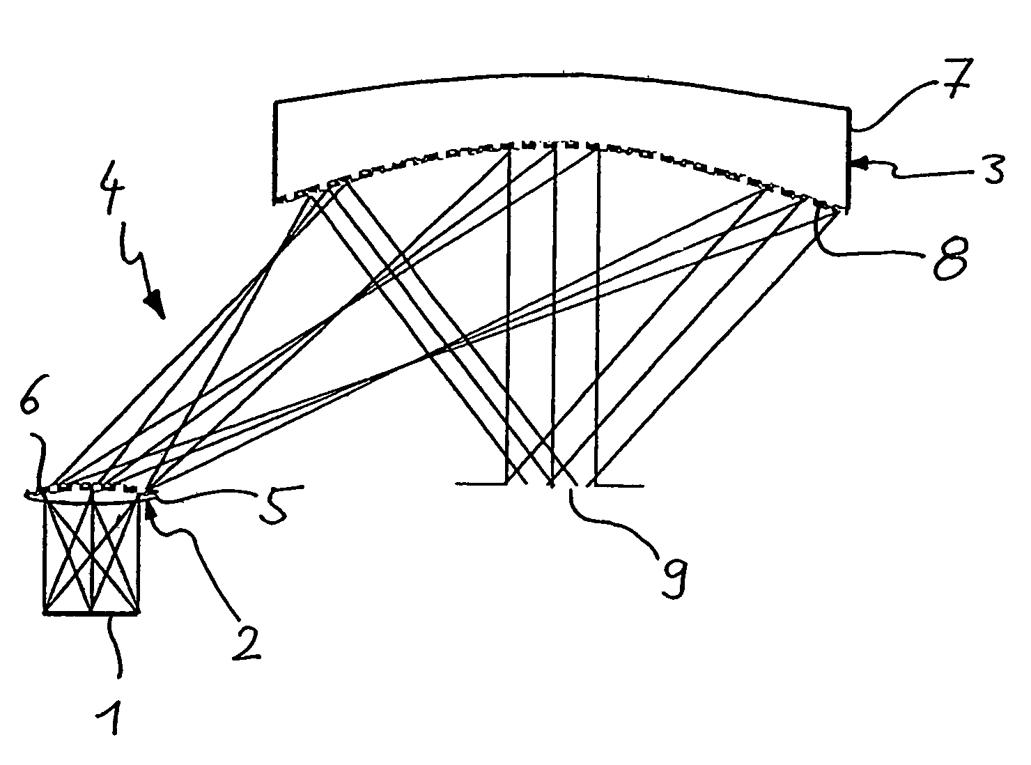
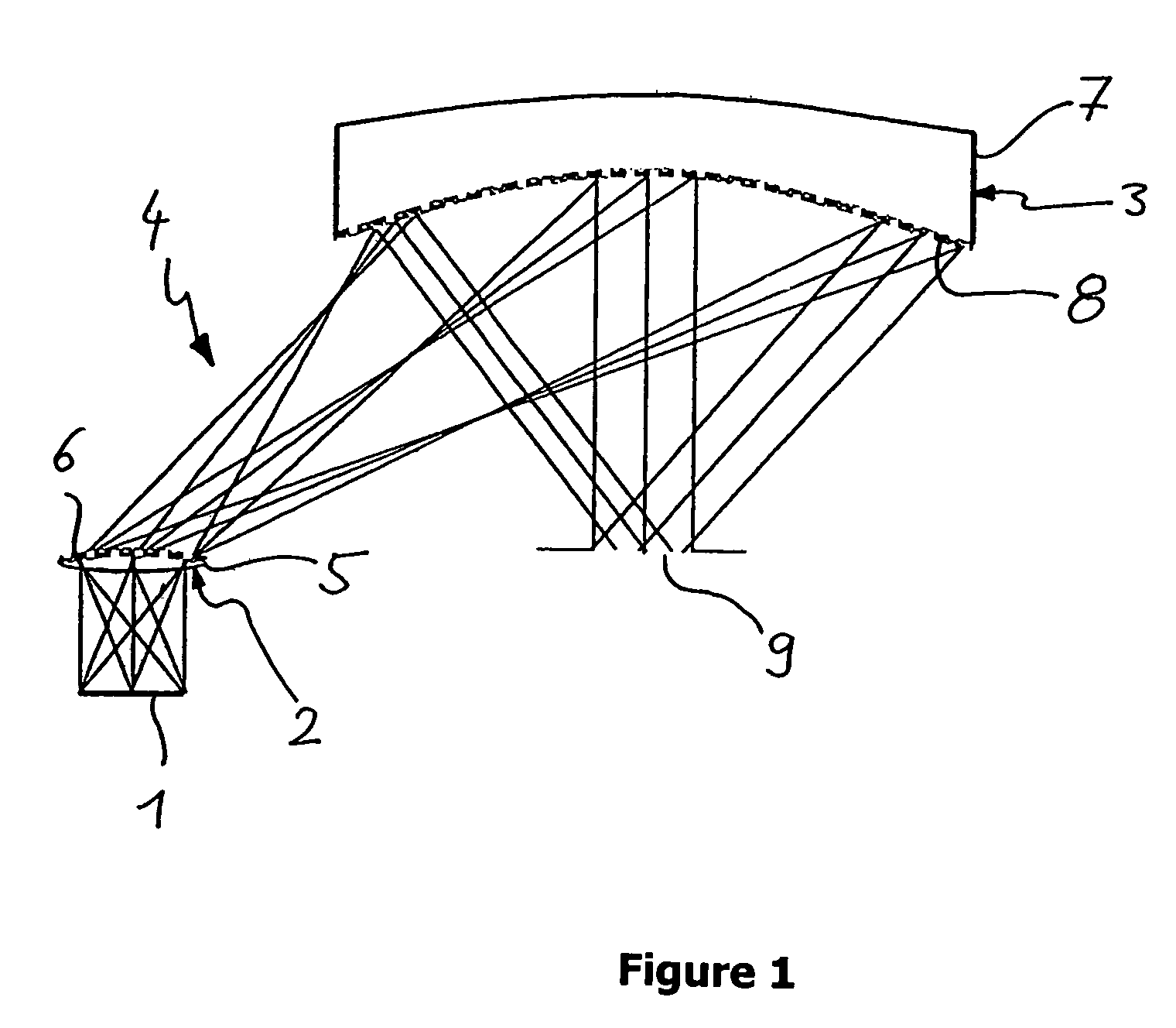
[0025]In this embodiment, the HMD device comprises an image-generating unit 1 for generating polychromatic images, said image-generating unit 1 being followed, in this order, by first partial optics 2 which are transmissive and by second partial optics 3 which are part reflective and part transmissive. Both partial optics 2 and 3 form a deflecting unit 4 and are each provided as hybrid optical units containing both refractive and diffractive elements.

[0026]As is evident from the schematic representation of FIG. 1, the first partial optics 2 comprise a first lens 5 (which is indicated in order to represent one or more refractive optical elements) as well as a first line grating 6 formed on the curved material interface of the first lens 5 facing away from the image-generating unit 1. In a similar manner, the second partial optics comprise a second lens 7 (shown in order to represent one or more refractive elements), with a second line grating 8 being provided on the curved material i...


PUM


Abstract

An HMD device including an image-generating unit for generating a polychromatic image and deflection optics having first and second partial optics. The deflection optics project the image such tat it is perceivable by a user wearing the HMD device. The two partial optics each contain a diffractive optical unit for beam deflection, which are designed such that their dispersion errors compensate each other.

Description

[0001]This application claims priority to German Application No. 103 16 533.9 filed Apr. 10, 2003. Said application is incorporated by reference herein.BACKGROUND OF THE INVENTION[0002]The present invention relates to an HMD device (Head Mounted Display device).[0003]In such devices, a wide field angle and a large exit pupil are generally desired. As a result, in known HMD devices, it is required to provide complex and large optics, making the weight of the HMD device disadvantageously high. Existing approaches using diffractive optics have the disadvantage that they only function in a monochromatic manner.[0004]In view of the above, it is the object of the present invention to provide an HMD device which has a compact and low-weight design and simultaneously allows polychromatic operation thereof.SUMMARY OF THE INVENTION[0005]According to the invention, the object is achieved by an HMD device comprising an image-generating unit for generating a polychromatic image, deflection optic...

Claims


Application Information

Patent Timeline
Patent Type & Authority Patents(United States)
IPC IPC(8): G02B27/14G09G5/00G02B27/02G02B5/18G02B27/00G02B27/01G02B27/44
CPCG02B5/1814G02B27/4211G02B27/4277G02B27/0172G02B5/18G02B2027/0116
Inventor EDELMANN, MARTIN
Owner CARL ZEISS SMT GMBH
Why Eureka
Try Eureka