Encapsulated sensor with external antenna

a sensor and antenna technology, applied in the field of electronic medical devices, can solve the problems of limited antenna area, small volume, and short transmission range of devices, and achieve the effects of increasing the active area of the antenna, increasing the overall size of the device, and improving coupling

Active Publication Date: 2007-11-13
BIOSENSE WEBSTER INC
View PDF19 Cites 46 Cited by
  • Summary
  • Abstract
  • Description
  • Claims
  • Application Information

AI Technical Summary

Benefits of technology

[0006]Embodiments of the present invention provide techniques for improving the coupling between a wireless device inside the body and a transmitter or receiver outside the body, by using a portion of the casing of the device as an antenna. The casing, which is typically sealed, comprises a conductive external area, which is coupled to circuitry inside the casing so as to serve as all or part of the device antenna. Using the outer surface of the casing as an antenna in this fashion increases the active area of the antenna, without necessarily increasing the overall size of the device.
[0007]In some embodiments of the present invention, the conductive external area of the casing is designed to contact conductive structures outside the device casing. For example, when the device is used in conjunction with a metal implant, the conductive area may contact the implant, in such a way that a part or all of the implant serves as the device antenna. Alternatively or additionally, when the casing of the device is in contact with conductive body fluids, such as blood or other electrolytes, ionic currents in the fluids may be used to enhance the antenna signals transmitted and received through the conductive area of the casing.
[0042]In another embodiment, inserting the casing includes bringing the electrically-conductive area into contact with an electrically-conductive body fluid while transmitting the signal, so as to increase a gain of the antenna in transmitting the signal.

Problems solved by technology

Unfortunately, the area of the antenna is limited by the available volume within the sensor casing.
For implantable devices, in particular, this volume is very small, and the transmission range of the device may be very short as a result.

Method used


Image

  • Encapsulated sensor with external antenna
  • Encapsulated sensor with external antenna
  • Encapsulated sensor with external antenna

Examples


Embodiment Construction

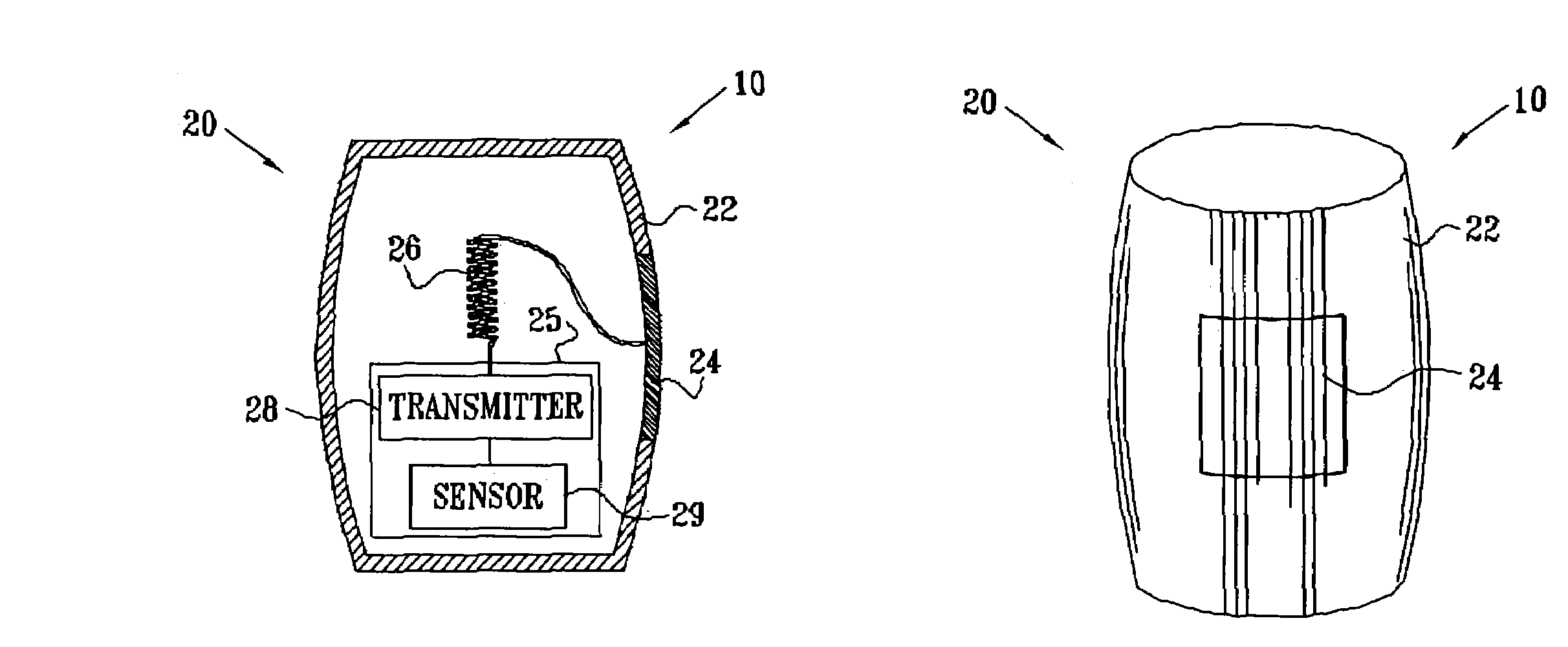
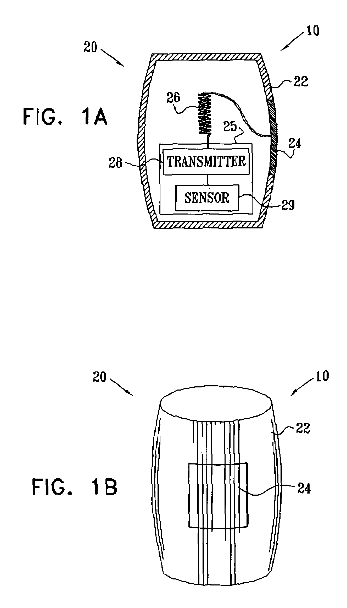
[0053]Reference is now made to FIGS. 1A and 1B, which schematically illustrate a wireless device 10 for use inside the body of a mammalian subject, in accordance with an embodiment of the present invention. FIG. 1A is a sectional view of the device, while FIG. 1B is a pictorial illustration of the device exterior. Device 10 comprises circuitry that is contained within a sealed casing 20. The casing comprises an insulating material 22, such as a ceramic or plastic material, with a conductive area 24, typically made of a suitable biocompatible metal. In this embodiment, the entire thickness of the casing in area 24 is metal, which is fastened and sealed to the surrounding insulating material 22 by a suitable metal / ceramic or metal / plastic seal, as is known in the art.

[0054]Device 10 comprises electrical circuitry 25, which is encapsulated inside casing 20. The circuitry typically comprises a transmitter 28, which is coupled to transmit signals via conductive area 24 to one or more rec...


PUM


Abstract

A medical device, for use inside a body of a mammalian subject, includes a casing adapted for insertion into the body of the mammalian subject, the casing having an outer surface and including an insulating material and an electrically-conductive material, which are arranged so that an area of the outer surface of the casing is electrically conductive. A transmitter is adapted to generate an electrical signal and is encapsulated in the casing and coupled to the conductive material so that the electrically-conductive area of the outer surface serves as an antenna for transmitting the signal to a receiver outside the body.

Description

FIELD OF THE INVENTION[0001]The present invention relates generally to electronic medical devices, and specifically to wireless transmission of radio signals to and from such devices within the body of a patient.BACKGROUND OF THE INVENTION[0002]The use of encapsulated, wireless sensors within a patient's body is known in the art. Typically, such sensors include a sensing circuit, for detecting a parameter of interest, and a transmitter, with a suitable antenna, for transmitting readings of the parameter to a receiver outside the body. In some applications, the sensor may also be capable of receiving signals and / or radiated power transmitted from outside the body. The parameter detected by the sensing circuit may be a physiological parameter, such as a local pressure, temperature or chemical characteristic (such as pH), or it may be a position parameter, indicative of the position coordinates of the sensor. Generally, all the elements of the sensor are encapsulated in a sealed casing...

Claims


Application Information

Patent Timeline
Patent Type & Authority Patents(United States)
IPC IPC(8): A61N1/00A61B1/00A61B5/00A61B5/01A61B5/04A61B5/06A61B5/07H01Q1/22H01Q1/38H01Q9/40H01Q9/42
CPCA61B5/0031A61B1/041A61B1/00016A61B5/06A61B5/062A61B1/00
Inventor GOVARI, ASSAF
Owner BIOSENSE WEBSTER INC
Why Eureka
Try Eureka