Shape-acceleration measurement device and method

a measurement device and acceleration technology, applied in the field of shape acceleration measurement devices and methods, can solve the problems of inability to provide continuous real-time measurement and/or tracking dynamic shapes, tilt sensor technologies do not measure dynamic acceleration, lack of calibrated, deformable, portable substrates to hold sensors and protect, etc., to improve the accuracy of prior art methods, accurate measurement, and low cost

Active Publication Date: 2007-11-20
MEASURAND INSTR INC
View PDF6 Cites 56 Cited by
  • Summary
  • Abstract
  • Description
  • Claims
  • Application Information

AI Technical Summary

Benefits of technology

[0012]The present invention provides for a calibrated combination of sensors, and measurement and calibration methods that allows accurate measurement of both static and dynamic shapes of deformation and acceleration in a single system that is optimized for field installation at low cost. It will be shown that by integrating angles along paths and measuring and differentiating angles within a field, it is possible to greatly improve on the accuracy of prior art methods. Further, packaging techniques are disclosed that combine measurement, shielding, and sealing functions, leading to low-cost, portable integrated measurement tools.
[0030]Desirably, in the above embodiment the field-measuring sensors are dual or triple axis accelerometers and the rotation sensor is a digital shaft encoder, and the rotatable joints are fitted with curvature sensors for increased accuracy when measuring dynamic shapes.

Problems solved by technology

A deficiency of the above tilt sensor methods is the inability to provide continuous real-time measurement and / or to track dynamic shapes.
Most of the current tilt sensor technologies do not measure dynamic acceleration such as s-waves during an earthquake.
A further deficiency is the lack of a calibrated, deformable, portable substrate to hold the sensors and protect them from water and mechanical forces.
A further deficiency is the requirement for a larger number of sensors because the tilt sensors are not arranged within a calibrated structure or a twist-free structure, so that magnetic measurement of orientation about the gravity vector is required.
A deficiency of 2 DOF bend-sensing arrays or 3 DOF bend-twist-sensing arrays in their most common form is their inability to measure accurately the small angles encountered in many applications including borehole measurements.
Although they can resolve small angles over a short time period, drift causes inaccuracies that are a problem for long-term measurements.
However, this leads to great cost and complexity that makes it unlikely they would be used for long-term measurement of deformations.
The measurements are subject to significant errors for all portions of the surface calculated beyond the location of any angular error.
Further, drift in the sensors can lead to inaccuracies in shape that must be corrected by putting the surfaces back into a previously captured pose and removing offsets to restore the measured shape to that of the captured pose.
However, the disadvantage of all prior-art tilt-sensing arrays is that measurements must be made while the shapes are unchanging.

Method used


Image

  • Shape-acceleration measurement device and method
  • Shape-acceleration measurement device and method
  • Shape-acceleration measurement device and method

Examples


Embodiment Construction

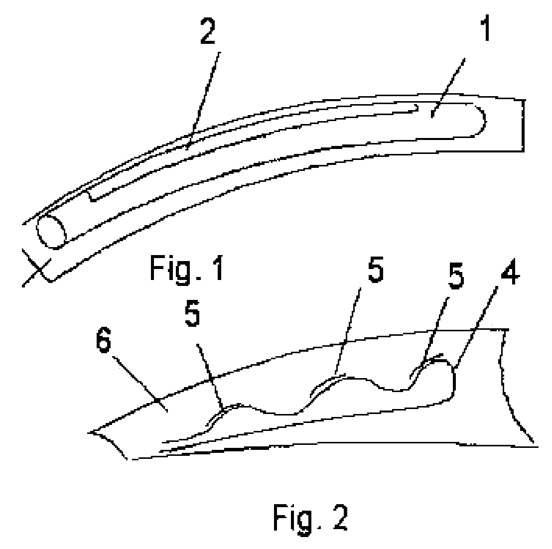
[0051]FIG. 1 shows a fiber optic sensor capable of sensing bend which is described in detail in Danisch '257. It comprises a fiber 1 treated to lose light on one side through a loss zone 2, preferably along the entire length over which bend is to be sensed. The optical design is such that bend is integrated along the treated portion of the fiber. The optical intensity transmitted through the fiber is modulated according to the net angular displacement between ends of the treated region, regardless of path. The sensor may be attached to a bendable substrate 3 to sense the bend of the substrate.

[0052]FIG. 2 shows an extension of the bend-sensing method of FIG. 1, which is explained in detail in Danisch '672. An optical fiber 4 has been sinuated along a substrate within a sensing region which is approximately the full length of the sinuations shown. On portions 5 of the fiber 1 approximating a 45 degree orientation to the long axis of the substrate, the fiber is treated to sense curvat...


PUM


Abstract

The present invention provides for a sensor array having at least one field-measuring sensor and at least one curvature-measuring sensor within a flexible substrate, the field-measuring sensors capable of providing orientation data of the flexible substrate relative to a field and the curvature-measuring sensors capable of providing relative orientation data within the substrate, for measuring dynamic and static shapes and vibration of geotechnical, structural and biological bodies.

Description

[0001]The present application claims priority to Canadian Patent Application No. 2,472,421 filed Jun. 25, 2004.FIELD OF THE INVENTION[0002]The present invention relates to a sensor array for measurement. More particularly, the present invention is directed to a method and apparatus for sensing the shape and acceleration of objects and pathways.BACKGROUND OF THE INVENTION[0003]It is well known in the fields of Geology and Earth Science to use tilt sensors to measure the paths of boreholes. Typically, a tilt sensor is a tubular form containing electrolytic, resistive, capacitive, ‘zero-displacement’, or micromachined silicon gravity sensors arranged to sense two degrees of freedom (DOFs) of tilt relative to the gravity field. Normally the two DOFs are orthogonal, and are termed x and y components of tilt. The tilt sensor may be lowered into a borehole and tilt data taken at intervals. Or, several tilt sensors may be arranged one above the other in the borehole and used to detect chang...

Claims


Application Information

Patent Timeline
Patent Type & Authority Patents(United States)
IPC IPC(8): G01B5/20A61B34/20E21B47/00G01B7/287G01B21/00G01B21/20G01C7/00G01C9/00G01P15/00G01P15/125G01P15/18G01V1/20
CPCG01P15/18G01P15/125G01P2015/0828
Inventor DANISCH, LEELOWERY-SIMPSON, MURRAY
Owner MEASURAND INSTR INC
Why Eureka
Try Eureka