Parallel serpentine cooled blade

a technology of serpentine cooled blades and parallel serpentine, which is applied in the direction of engines, machines/engines, mechanical equipment, etc., can solve the problems of inability to meet the substantially long life requirements of modern gas turbine engines, significant affecting the efficiency and performance of the entire engine, and additional centrifugal force problems, etc., to achieve the effect of improving internal cooling

Inactive Publication Date: 2007-11-20
GENERAL ELECTRIC CO
View PDF24 Cites 72 Cited by
  • Summary
  • Abstract
  • Description
  • Claims
  • Application Information

AI Technical Summary

Problems solved by technology

Minor changes in cooling configurations of these components have significant affect on the cooling performance thereof, and in turn significantly affect efficiency and performance of the entire engine.
Impingement cooling of turbine rotor blades presents the additional problem of centrifugal force as the blades rotate during operation.
Accordingly, turbine rotor blades typically do not use separate impingement baffles therein since they are impractical, and presently cannot meet the substantially long life requirements of modern gas turbine engines.
Instead, impingement cooling a turbine rotor blade is typically limited to small regions of the blade such as the leading edge or pressure or suction sidewalls thereof.
The ability to introduce significant impingement cooling in a turbine rotor blade is a fundamental problem not shared by the nozzle stator vanes.
And, impingement cooling results in a significant pressure drop of the cooling air, and therefore requires a corresponding driving pressure between the inside and outside of the airfoils during operation.

Method used


Image

  • Parallel serpentine cooled blade
  • Parallel serpentine cooled blade
  • Parallel serpentine cooled blade

Examples


Embodiment Construction

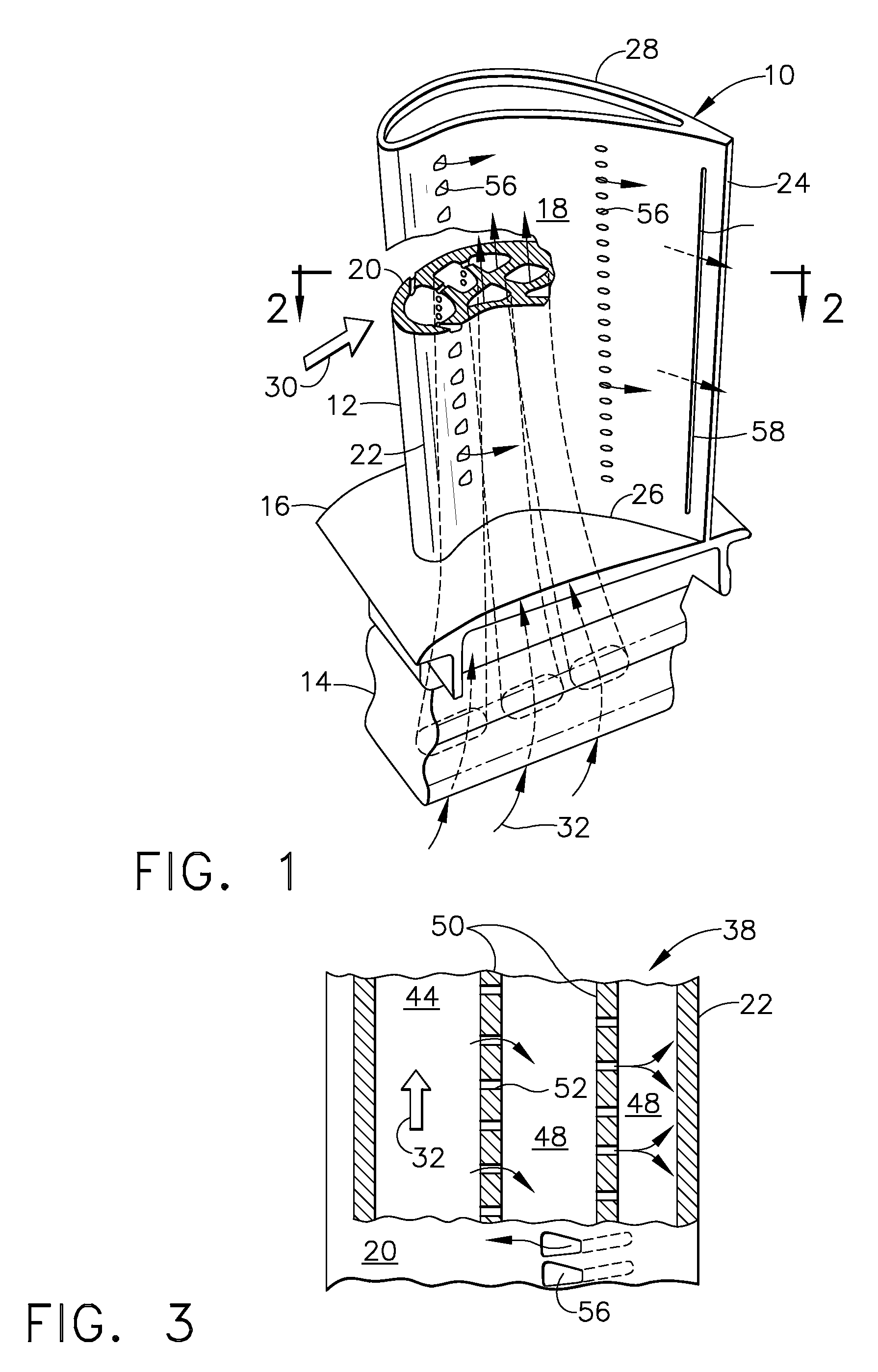
[0025]Illustrated in FIG. 1 is a gas turbine rotor blade 10 for use in a conventional gas turbine engine, such as a turbofan aircraft engine (not shown). The blade itself is typically manufactured using conventional casting techniques, and includes an airfoil 12 integrally joined to a mounting dovetail 14 at a platform 16.

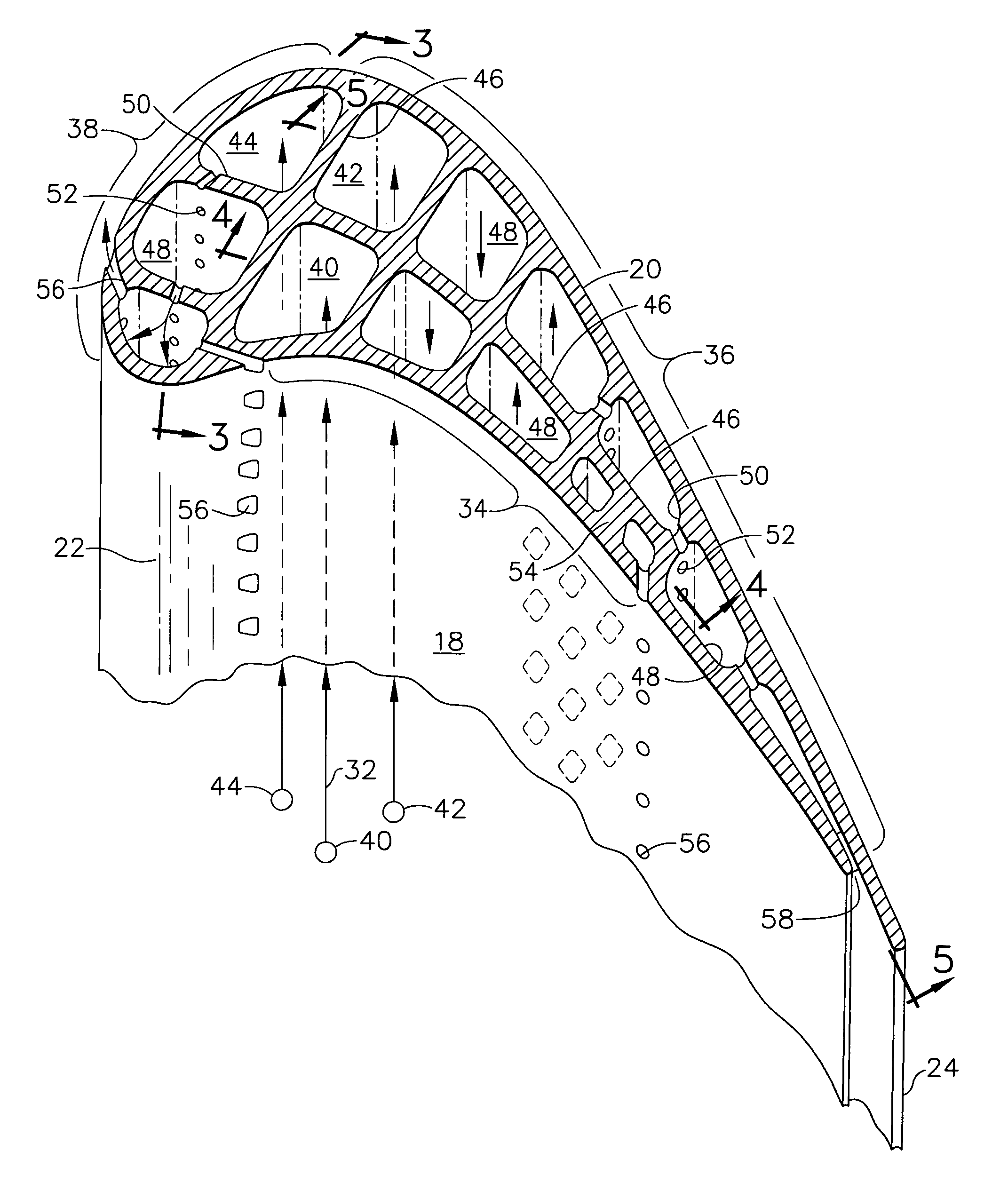
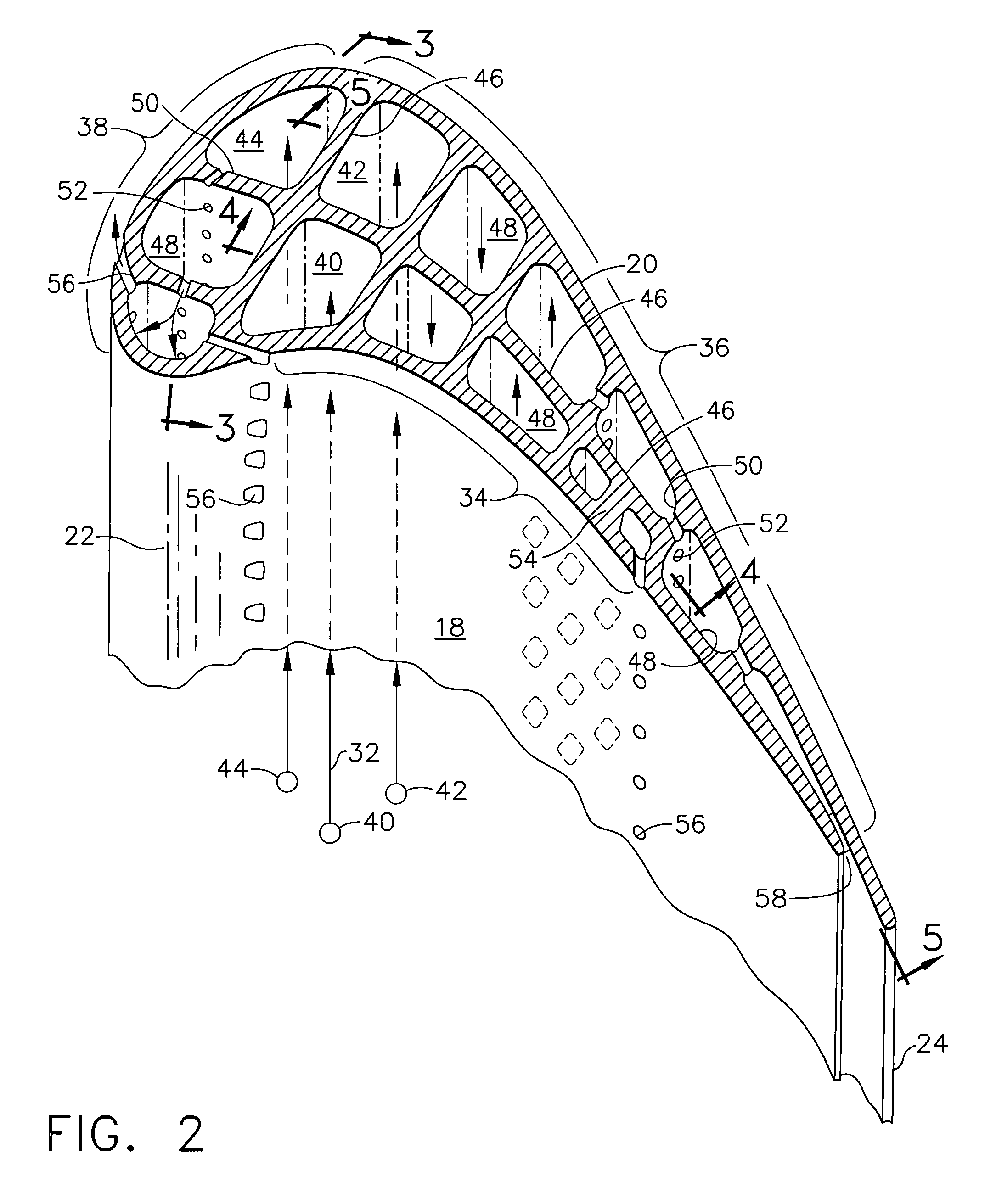
[0026]The airfoil includes a generally concave pressure sidewall 18, and a circumferentially opposite, generally convex suction sidewall 20 integrally joined together at chordally opposite leading and trailing edges 22,24. The airfoil also extends longitudinally or radially in span from a radially inner root 26 at the platform 16 to a radially opposite tip 28.

[0027]During operation, the blade is mounted in a supporting rotor disk (not shown) by trapping the dovetail 14 in a complementary dovetail slot. In this way, centrifugal forces generated in the blade during rotary operation are carried through the lobes or tangs of the dovetail into the supporting rotor disk....


PUM


Abstract

A turbine blade includes an airfoil having opposite pressure and suction sidewalls joined together at opposite leading and trailing edges and extending longitudinally from root to tip. A plurality of independent cooling circuits are disposed inside the airfoil correspondingly along the pressure and suction sidewalls thereof. A first serpentine circuit is disposed along the pressure sidewall. A second serpentine circuit is disposed along the suction sidewall in parallel with the first circuit. And a third impingement circuit is disposed at the leading edge forward of the first and second circuits.

Description

BACKGROUND OF THE INVENTION[0001]The present invention relates generally to gas turbine engines, and, more specifically, to turbine airfoil cooling.[0002]In a gas turbine engine air is pressurized in a compressor and mixed with fuel in a combustor for generating hot combustion gases. Energy is extracted from the combustion gases in a high pressure turbine which powers the compressor, and further in a low pressure turbine which produces output power such as driving a fan in a typical turbofan aircraft engine application.[0003]The high pressure turbine first receives the hottest combustion gases and is typically cooled for enhancing its durability and life. A high pressure turbine nozzle initially directs the hot combustion gases into the first row of high pressure turbine rotor blades extending radially outwardly from a supporting rotor disk.[0004]The vanes and blades have suitable airfoil configurations for efficiently extracting energy from the combustion gases. The vane airfoils a...

Claims


Application Information

Patent Timeline
Patent Type & Authority Patents(United States)
IPC IPC(8): F01D5/18
CPCF01D5/187F05D2260/202Y02T50/676F05D2250/185Y02T50/60
Inventor LEE, CHING-PANGWADIA, ASPI RUSTOMBRASSFIELD, STEVEN ROBERT
Owner GENERAL ELECTRIC CO
Why Eureka
Try Eureka