Vibration damping for a cue stick

a cue stick and vibration damping technology, which is applied in the field of vibration damping for cue sticks, can solve the problems of affecting the trajectory of the cue ball, the shaft of the cue stick is subject to substantial vibration,

Inactive Publication Date: 2007-11-20
COSTAIN PAUL D +1
View PDF51 Cites 8 Cited by
  • Summary
  • Abstract
  • Description
  • Claims
  • Application Information

AI Technical Summary

Benefits of technology

[0002]In instances where a player attempts to impart spin on the cue ball (i.e., english) to direct a particular type of shot, the free end of a cue stick strikes the ball in a line that does not travel through the center of mass of the ball. As a result, substantial force may be generated in a direction orthogonal to the axis of the cue stick. In particular, the shaft of the cue stick, being thinner and more flexible than the butt, is subject to substantial vibration, which may affect the trajectory of the cue ball. Thus, players must correct for this phenomena when imparting english to their shots. Therefore, a need exists for a cue stick, or shaft of a cue stick, that is less subject to vibration, which may reduce need for players to correct deflection associated with a shot having english.
[0003]Simultaneously, players desire a cue stick that is stiff such that the efficient transmission of momentum from cue stick to ball is maintained when a shot is performed. As well, players often favor a cue stick which has the weight distribution, and transmits forces to the hand of a player in the manner of, a wooden cue. Though cues made of materials other than wood exist, such cues lack many of the properties of wooden cues that players desire. In particular, many materials tend to accentuate the vibration of a cue stick. Use of such materials may substantially alter the trajectory of a shot when the material is incorporated near the ball strike end of the stick. Use of light, non-structural materials (e.g., cotton) may occupy a large relative volume of the cue stick to achieve sufficient vibration damping. Such a loss of volume of structural material may substantially affect the “feel” of such cue sticks when a ball is struck.
[0004]In some embodiments of the invention, a vibration reducing shaft for a cue stick includes a shaft configured to form an axially rigid ensemble when mated with another segment of the cue stick. The shaft includes a damping material with a density higher than wood; the damping material may also be a piezoelectric material without regard to its density. The damping material is configured to reduce the vibration of the shaft when a ball strikes the free end of the shaft. Thus, the damping material may provide substantial vibration reduction without occupying a large relative volume of the shaft such that the force transmission properties of the shaft are adversely affected.

Problems solved by technology

In particular, the shaft of the cue stick, being thinner and more flexible than the butt, is subject to substantial vibration, which may affect the trajectory of the cue ball.
Though cues made of materials other than wood exist, such cues lack many of the properties of wooden cues that players desire.
Use of such materials may substantially alter the trajectory of a shot when the material is incorporated near the ball strike end of the stick.
Such a loss of volume of structural material may substantially affect the “feel” of such cue sticks when a ball is struck.
Thus, the damping material may provide substantial vibration reduction without occupying a large relative volume of the shaft such that the force transmission properties of the shaft are adversely affected.

Method used


Image

  • Vibration damping for a cue stick
  • Vibration damping for a cue stick
  • Vibration damping for a cue stick

Examples


Embodiment Construction

[0012]A description of preferred embodiments of the invention follows.

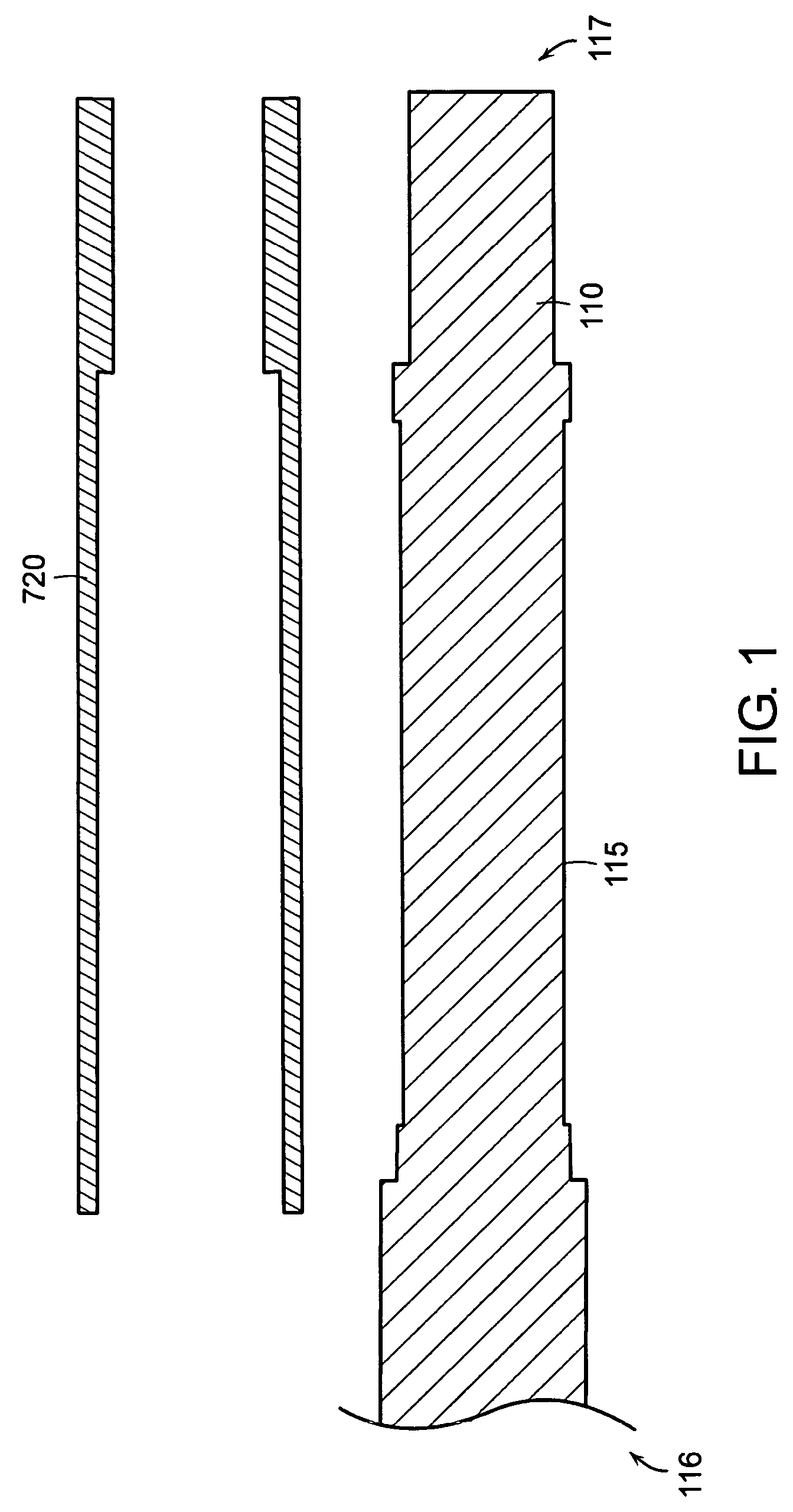
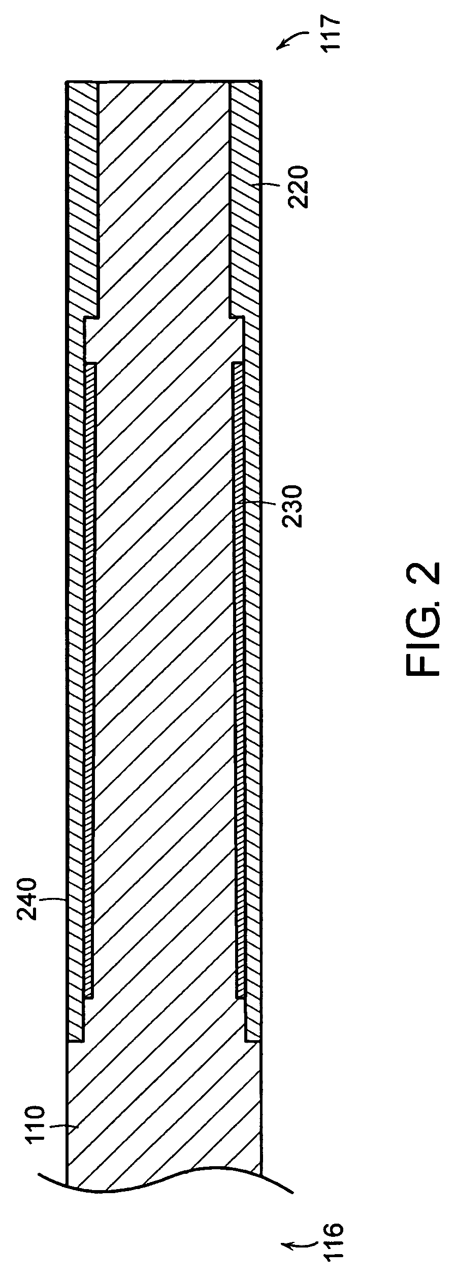
[0013]FIG. 1 depicts pieces that may be utilized to form a vibration reducing shaft, in accordance with an embodiment of the invention. A shaft body 110 has a free end side 116 and a butt end side 117. A portion of the body 110 is configured to receive a sleeve 120. When the sleeve 120 is fitted over the body 110, as shown in FIG. 2, the combination has a substantially smooth outer surface 240. The shaft body 110 is also configured with a circumferentially formed sunken tier 115 around the shaft body 110. The sunken tier 115 forms an annular region when the sleeve 120 is combined with the shaft body 110. A damping material 230 is placed in the annular region. The damping material 230 reduces the vibration of the shaft in the radial direction when the free end 116 of the shaft strikes a ball.

[0014]The shaft body 110 is typically constructed of wood, though shaft bodies constructed with other materials are also with...


PUM


Abstract

In an embodiment of the invention, a vibration damping shaft of a cue stick comprises a shaft that is configured to form an axially rigid ensemble by mating with another segment of a cue stick. The shaft includes damping material that reduces the vibration of the shaft when a ball strikes the shaft. The damping material may have a density greater than wood. The damping material may be configured as an annular region in the shaft, or in any other configuration that reduces shaft vibration. Damping materials include composites, such as piezoelectric materials, with fibers that are generally aligned to reduce shaft vibration. Another embodiment of the invention utilizes a universal shaft insert, allowing the shaft to fit another segment of a cue stick having a particular joint pin configuration. Features of the a vibration damping shaft may also be incorporated into a cue stick that is not collapsible.

Description

BACKGROUND OF THE INVENTION[0001]Cue sticks for pool and billiards game play are typically constructed to efficiently transmit momentum from the cue to a ball being struck. Cue sticks oftentimes are constructed of wood, which possesses particular properties that affect the way forces are transmitted to the hand of a player.SUMMARY OF THE INVENTION[0002]In instances where a player attempts to impart spin on the cue ball (i.e., english) to direct a particular type of shot, the free end of a cue stick strikes the ball in a line that does not travel through the center of mass of the ball. As a result, substantial force may be generated in a direction orthogonal to the axis of the cue stick. In particular, the shaft of the cue stick, being thinner and more flexible than the butt, is subject to substantial vibration, which may affect the trajectory of the cue ball. Thus, players must correct for this phenomena when imparting english to their shots. Therefore, a need exists for a cue stick...

Claims


Application Information

Patent Timeline
Patent Type & Authority Patents(United States)
IPC IPC(8): A63D15/08
CPCA63D15/08
Inventor COSTAIN, PAUL D.STROUD, BILL
Owner COSTAIN PAUL D
Why Eureka
Try Eureka