Apparatus for and method of improving position and time estimation of radio location devices using calibrated pulse shapes

a radio location device and pulse shape technology, applied in the field of spreadspectrum systems, can solve the problems of affecting the synchronization process of the receiver with the direct-path signal, distortion may induce errors in the synchronization process of the receiver, and the received signal is corrupted, so as to avoid calibration operations, improve the estimation of positions and time, and detect satellite malfunctions readily.

Active Publication Date: 2007-11-20
NOVATEL INC
View PDF9 Cites 20 Cited by
  • Summary
  • Abstract
  • Description
  • Claims
  • Application Information

AI Technical Summary

Benefits of technology

[0022]In the differential mode operations, the remote receiver adjusts the position correction data provided by the reference receiver using “correlation value corrections,” which correspond to the differences between the reference pulse shape models that are maintained by or are applicable to the two receivers. These differences translate to differences in the corresponding pseudoranges, that is, to range biases. Accordingly, the receiver uses the reference pulse shapes in the differential mode operations to remove the range biases, and thus, produce improved estimations for positions and time, as described in more detail below.
[0023]In signal quality management operations, the reference pulse shapes may be used essentially to establish the underlying correlation values to which correlation values measured in real time are compared. The receiver then uses the differences between the correlation values determined from the reference pulse shape and the measured correlation values, to determine if a given satellite is malfunctioning. Further, the reference pulse shapes may be used to determine range biases between receiver channels that use different correlation techniques. As described in more detail below, the receiver uses the reference pulse shapes in the signal quality management operations in order to more readily detect satellite malfunction, and also, to avoid calibration operations that are otherwise required each time the receiver powers up.
[0025]The receiver uses the calibrated reference pulse shapes in multipath mitigation processing operations in place of the conventional reference pulse shapes, to aid in distinguishing between the direct path signal and one or more multipath signals in which the chip transition times are close to those of the direct path signal. The receivers use the calibrated reference pulse shapes in the differential operating mode, to provide more precise position and time estimates by eliminating more of the range bias from the differential position correction data provided by the reference receiver. Further, the receiver uses the calibrated reference pulses in signal quality management operations in order to more readily determine satellite malfunction.

Problems solved by technology

The sources of the errors in the calculations include satellite state errors, such as, for example, the differences between the computed and actual time bases for the satellites and the computed and actual positions of the satellites.
Another source of errors is the corruption of the received signal by multipath signals, which are signals that travel along different paths and are reflected to the receiver from the ground, bodies of water, nearby buildings, etc.
The distortion adversely affects code synchronization operations because the correlation measurements, which measure the correlation between the local PRN code and the received signal, are based on the entire received signal—including the multipath components thereof.
Accordingly, the distortion may induce errors in the receiver synchronization process with the direct-path signal.
In such situations, the known prior systems may introduce residuals and associated tracking errors into the processing based on the differences between the reference pulse shapes and the pulse shapes that correspond to the transmitted codes.
The other techniques may, however, result in the function having a shape other than the traditional triangular shape.

Method used


Image

  • Apparatus for and method of improving position and time estimation of radio location devices using calibrated pulse shapes
  • Apparatus for and method of improving position and time estimation of radio location devices using calibrated pulse shapes
  • Apparatus for and method of improving position and time estimation of radio location devices using calibrated pulse shapes

Examples


Embodiment Construction

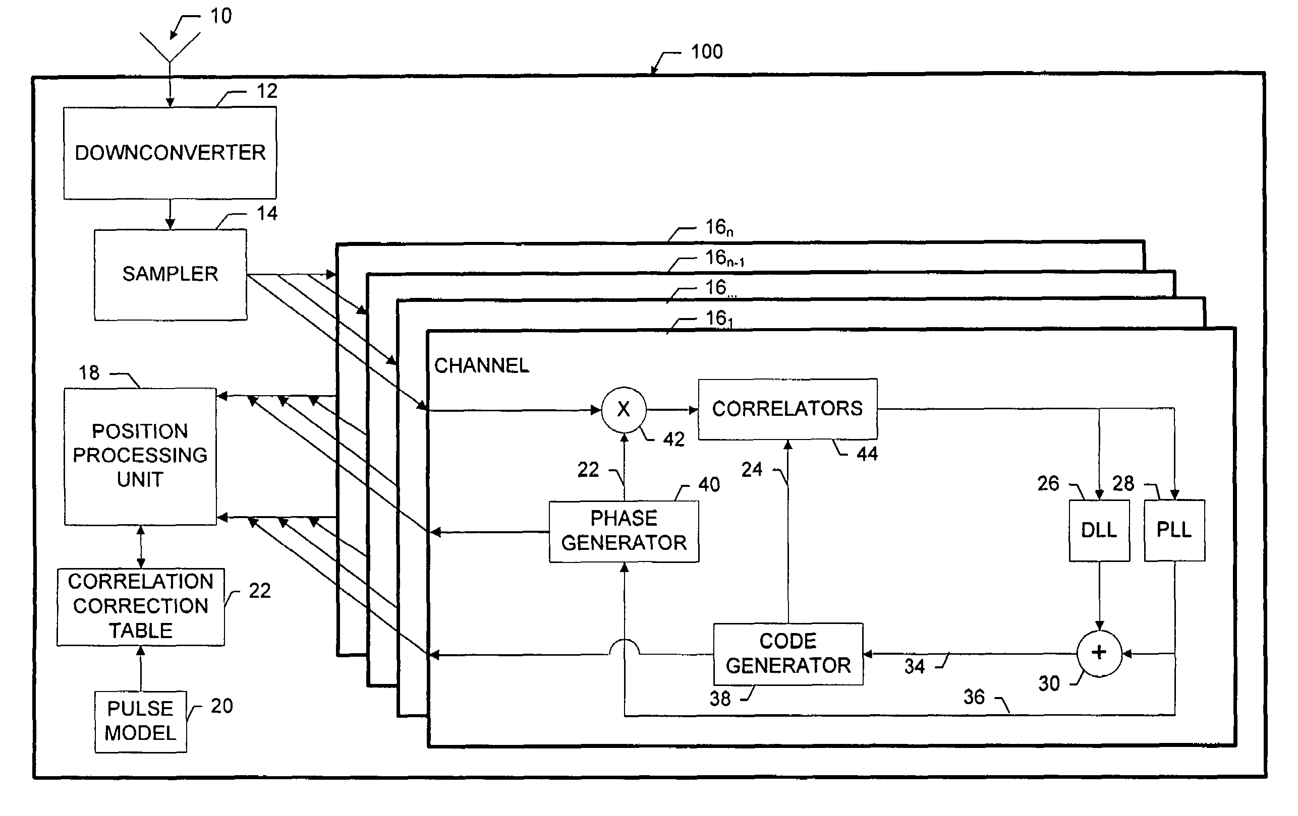
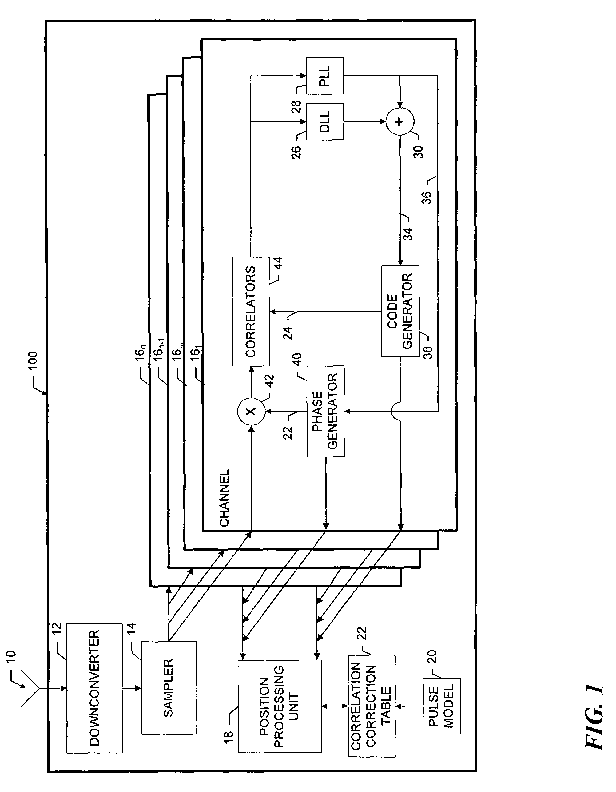
[0035]As shown in FIG. 1 a receiver 100 that incorporates the invention includes an antenna 10 that receives spread spectrum signals that are transmitted by, for example, GPS satellites (not shown). A downconverter 12 translates the incoming satellite signals to an intermediate frequency. A sampler 14 samples the downconverted signal, and provides the samples to a plurality of data correlation channels 161 . . . 16n. For convenience, only one channel 161 is shown in expanded detail.

[0036]A given correlation channel 16 acquires and tracks the satellite signal in a well-known manner using correlators 44, a carrier phase tracking loop 36 and a code tracking loop 34. At predetermined times, the various channels provide ranging data to a position processing unit 18, which determines global position and time in a known manner. The position processing unit 18 also provides overall control of the correlation channels, such as assigning the signals from particular satellites to the channels ...


PUM


Abstract

GPS receivers utilize reference pulse shapes in operations to determine estimates of position and time to correct for range biases in differential operations and in signal quality operations. The reference pulse shapes may be code family based, or may be calibrated on a per satellite basis, to incorporate therein the affects of the satellite hardware on the transmitted signals. The receivers may further manipulate the calibrated pulse shape models on a per receiver basis, to incorporate therein the affects of the IF and RF paths through the respective receivers. The calibrated reference pulse shapes may also be used in multipath mitigation processing operations for the respective codes, to produce estimates of the direct path signals and corrections for the carrier and code tracking loops.

Description

BACKGROUND OF THE INVENTION[0001]1. Field of the Invention[0002]The invention relates generally to spread-spectrum systems and, in particular, to systems that utilize reference pulse shapes of the correlation functions to improve the determination of the position and time estimation of radio location devices, such as GPS receivers.[0003]2. Background Information[0004]One example of a system that utilizes broadcast spread-spectrum signals is a global positioning system, such as, GPS, GLONAS or GALILEO systems. The system receivers determine their global positions based on the signals they receive from associated satellites. The broadcast spread-spectrum signal consists of a carrier that is modulated by at least one pseudorandom code, such as a binary PRN code that is a pseudo random sequence of one and zeros that periodically repeat. The ones and zeros in the PRN code are referred to as “code chips,” and the transitions in the code from one to zero or zero to one, which occur at “cod...

Claims


Application Information

Patent Timeline
Patent Type & Authority Patents(United States)
IPC IPC(8): G01S5/14G01S19/46
CPCG01S19/22G01S19/43G01S19/41G01S19/235
Inventor MANZ, ALLAN
Owner NOVATEL INC
Why Eureka
Try Eureka