
In-band QoS signaling reference model for QoS-driven wireless LANs

a wireless lan and reference model technology, applied in the field of communication and networking, can solve the problems of not supporting qos transport, unable to provide asynchronous and low-throughput best-effort data services, and operate on a distributed contention or simplified polling, etc., to achieve the effect of expanding the functionality of the architectural reference model

Inactive Publication Date: 2007-11-20
AMERICAN TELEPHONE & TELEGRAPH CO
View PDF72 Cites 42 Cited by
  • Summary
  • Abstract
  • Description
  • Claims
  • Application Information

AI Technical Summary

Benefits of technology

This solution enhances QoS support in WLANs, improving bandwidth utilization and channel throughput, allowing for more efficient transport of multimedia services by prioritizing and managing data transmission opportunities based on QoS parameters.

Problems solved by technology

Unfortunately, wireless local-area networks (WLANs), such as currently specified by IEEE P802.11 / 1999, do not support QoS transport and operate on a distributed contention or simplified polling basis.
Consequently, only asynchronous and low-throughput best-effort data services are provided.

Method used


Image

  • In-band QoS signaling reference model for QoS-driven wireless LANs
  • In-band QoS signaling reference model for QoS-driven wireless LANs
  • In-band QoS signaling reference model for QoS-driven wireless LANs

Examples


Embodiment Construction

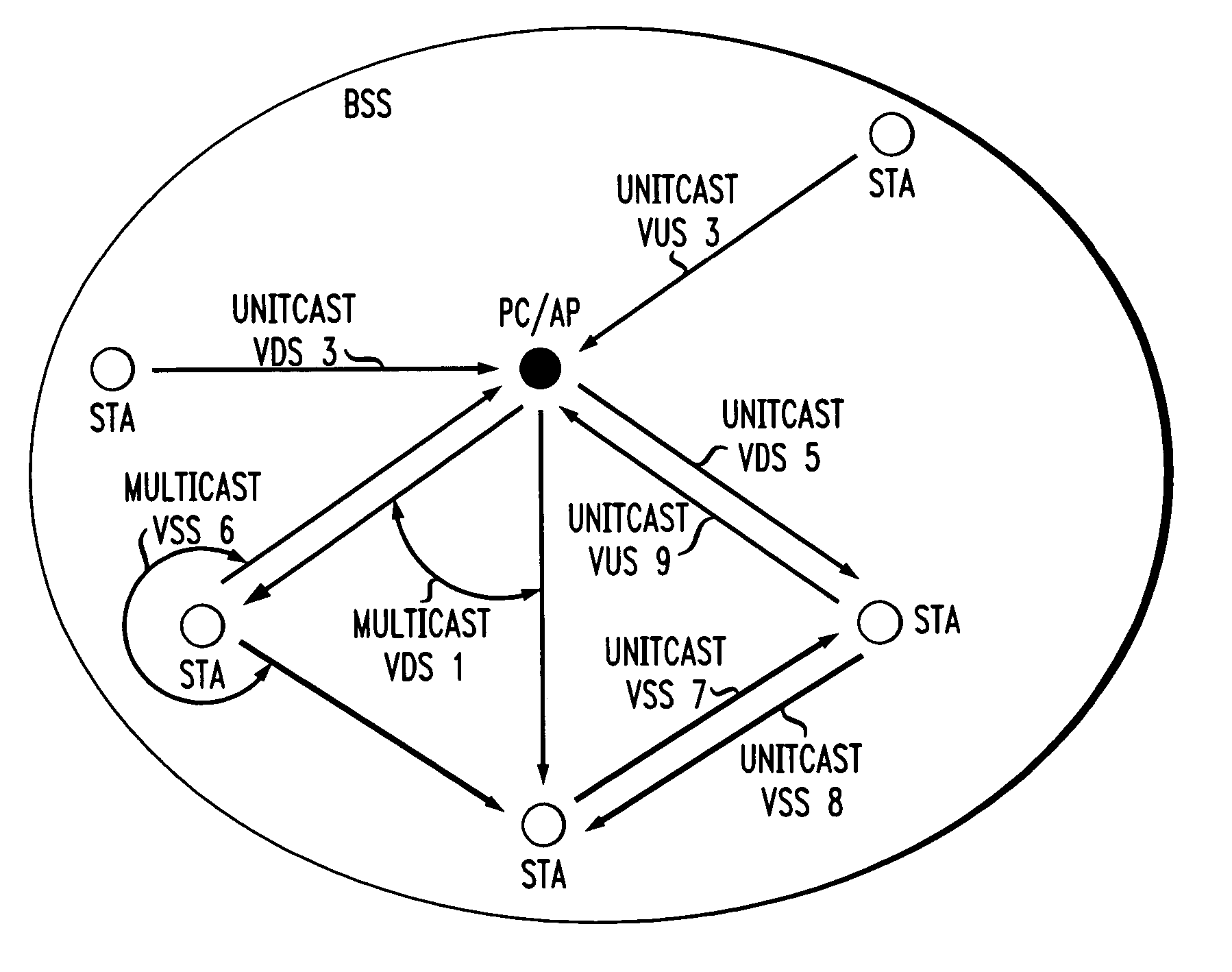
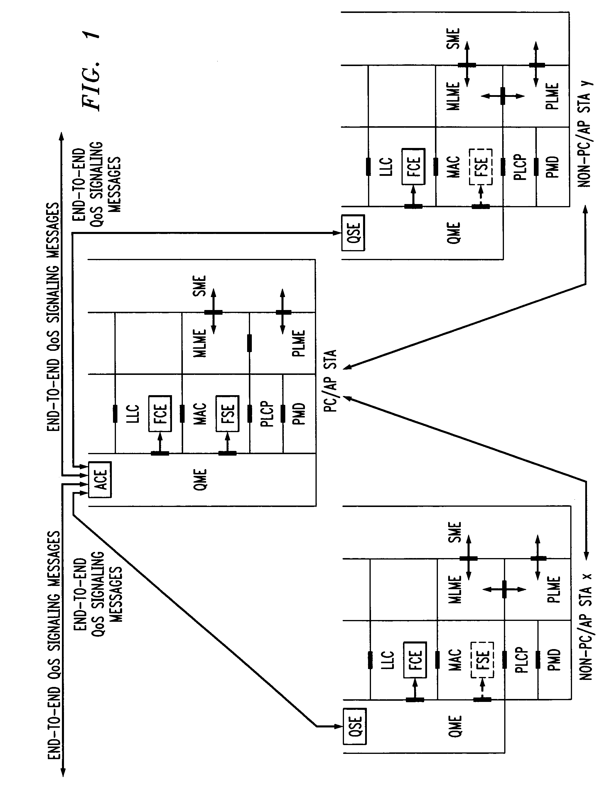
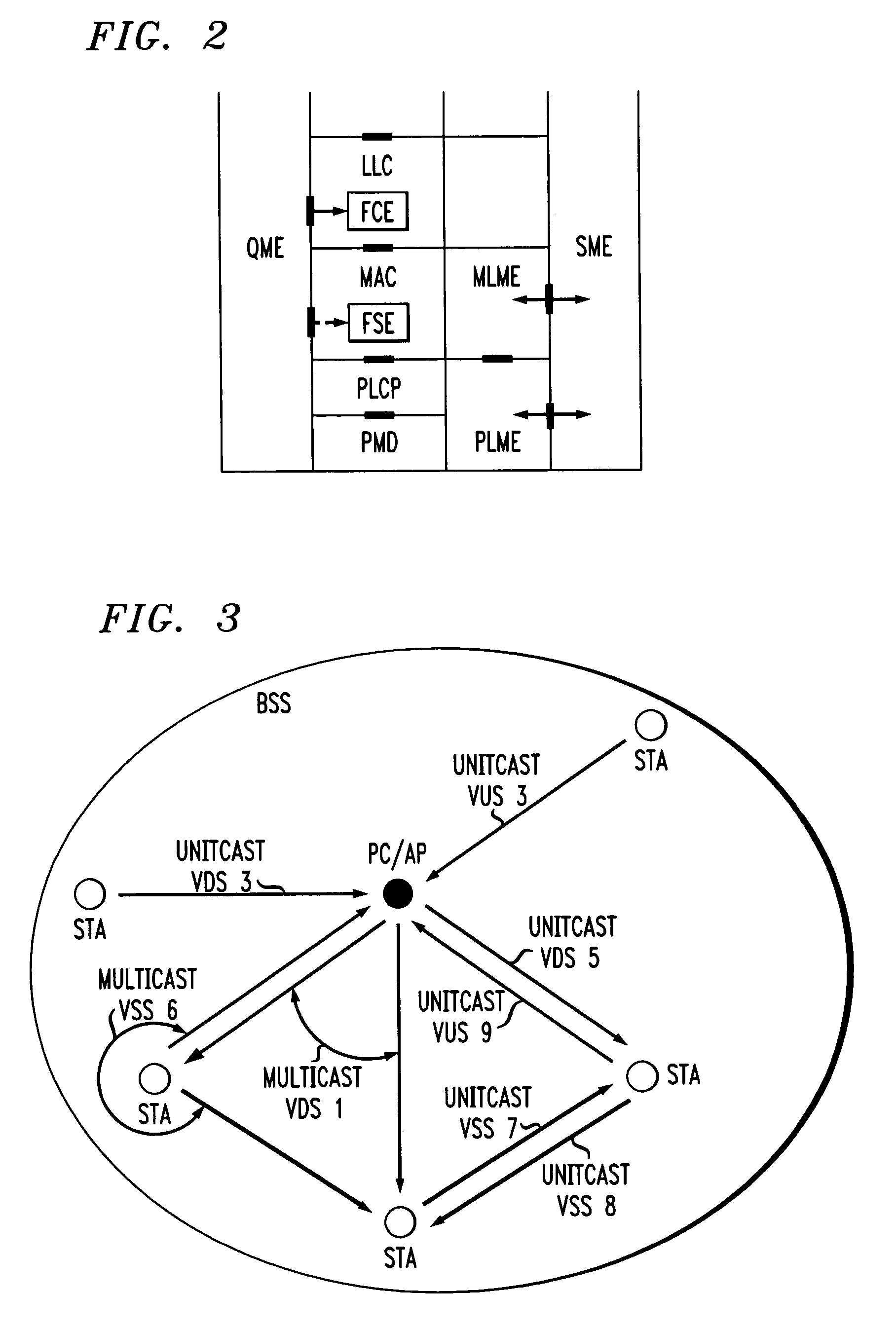
[0042]The present invention provides an architectural reference model that integrates the lower layers (link and PHY layers) of a WLAN, as currently specified by IEEE P802.11 / 1999, with the higher layers (network and higher layers) that appear in the ISO / IEC basic reference model of Open Systems Interconnection (OSI) (ISO / IEC 7498-1), but not in IEEE P802.11 / 1999. Both the IEEE P802.11 / 1999 and the ISO / IEC 7498-1 standards are incorporated by reference herein. Additionally, the present invention provides end-to-end QoS mechanisms. Such integration instills the QoS parameter values from the higher layers into the lower layers, and enables the lower layers to provide QoS traffic transport and improved channel throughput.

[0043]Compared to the existing reference model, as specified in IEEE P802.11 / 1999, the present invention introduces an admission control entity (ACE), a QoS management entity (QME), a frame classification entity (FCE), and a frame scheduling entity (FSE) for a point co...


PUM


Abstract

A station, such as a point coordinator (PC) or a non-PC station, in a basic service set (BSS) in a wireless local area network (WLAN) is disclosed. The station includes a frame classification entity (FCE), a frame scheduling entity (FSE) and a QoS management entity (QME). The FCE is logically located in a logical link control (LLC) layer of the station and has a classification table containing at least one classifier entry. Each classifier entry contains a virtual stream identifier (VSID) and a frame classifier associated with a user session. The FCE receives a data frame associated with the user session, which can be one of a voice session, a video session, a data session and a multimedia session. The data frame contains in-band quality of service (QoS) signaling information for the user session. The FCE classifies the received data frame to a selected VSID contained in a classifier entry in the classification table based on a match between an in-band frame classification information contained in the received frame and the frame classifier contained in the classifier entry. The FSE is logically located in a medium access control (MAC) sublayer of the station and has a frame scheduling table containing at least one entry. Each entry in the frame scheduling table contains a VSID and a QoS parameter set associated with a user session identified by the VSID. The FSE is responsive to the classified data frame by scheduling a transmission opportunity (TO) for the classified data frame based on the at least one QoS parameter value associated with the VSID and characterizing the user session. The QME interfaces with the FCE and The FSE.

Description

CROSS-REFERENCE TO RELATED APPLICATIONS[0001]This is a continuation of U.S. application Ser. No. 09 / 616,901 filed Jul. 14, 2000, now U.S. Pat. No. 6,804,222 which is incorporated by reference herein.[0002]The present application is related to:[0003]application Ser. No. 09 / 616,900 entitled An Architectural Reference Model for QoS-Driven Wireless LANs, invented by J.-M. Ho, and filed Jul. 14, 2000;[0004]application Ser. No. 09 / 617,083 entitled Virtual Streams for QoS-Driven Wireless LANs, invented by J.-M. Ho and W. Lin, and filed Jul. 14, 2000;[0005]application Ser. No. 09 / 616,897 entitled Admission Control for QoS-Driven Wireless LANs, invented by W. Lin and J.-M. Ho, and filed Jul. 14, 2000;[0006]application Ser. No. 09 / 616,896 entitled Frame Classification for QoS-Driven Wireless LANK, invented by J. M. Ho and W. Lin, and filed Jul. 14, 2000;[0007]application Ser. No. 09 / 617,493 entitled Frame Scheduling for QoS-Driven Wireless LANs, invented by J.-M. Ho and W. Lin, and filed Jul....

Claims


Application Information

Patent Timeline
Patent Type & Authority Patents(United States)
IPC IPC(8): H04Q7/24H04L12/28H04L12/56H04W8/26H04W72/12H04W76/04H04W84/12H04W92/04
CPCH04L12/66H04W72/1236H04W84/12H04W72/543
Inventor LIN, WEIHO, JIN-MENG
Owner AMERICAN TELEPHONE & TELEGRAPH CO
Learn More