Induction resistivity imaging principles and devices in oil based mud

a technology of induction resistivity and imaging principles, applied in the field of well logging, can solve the problems of not addressing the problem of borehole rugosity and its effect on induction measurement, not providing a complete coverage, and generally not addressing the problem of “seeing” into the earth formation

Active Publication Date: 2007-11-20
BAKER HUGHES HLDG LLC
View PDF14 Cites 29 Cited by
  • Summary
  • Abstract
  • Description
  • Claims
  • Application Information

AI Technical Summary

Problems solved by technology

The Dory patent discloses the use of an acoustic sensor in combination with pad mounted electrodes, the use of the acoustic sensors making it possible to fill in the gaps in the image obtained by using pad mounted electrodes due to the fact that in large diameter boreholes, the pads will necessarily not provide a complete coverage of the borehole.
The prior art identified above does not address the issue of borehole rugosity and its effect on induction measurements.
Being primarily high resolution imaging applications, the problem of “seeing” into the earth formation is generally not addressed.
In addition, usually the effect of mud resistivity on the measurements is not addressed.

Method used


Image

  • Induction resistivity imaging principles and devices in oil based mud
  • Induction resistivity imaging principles and devices in oil based mud
  • Induction resistivity imaging principles and devices in oil based mud

Examples


Embodiment Construction

[0030]Before discussing specific methods and hardware for induction resistivity imaging in oil based mud, the principles on which such methods and hardware should be based are discussed. The analysis herein includes the effect of borehole rugosity, something that has hitherto been not addressed.

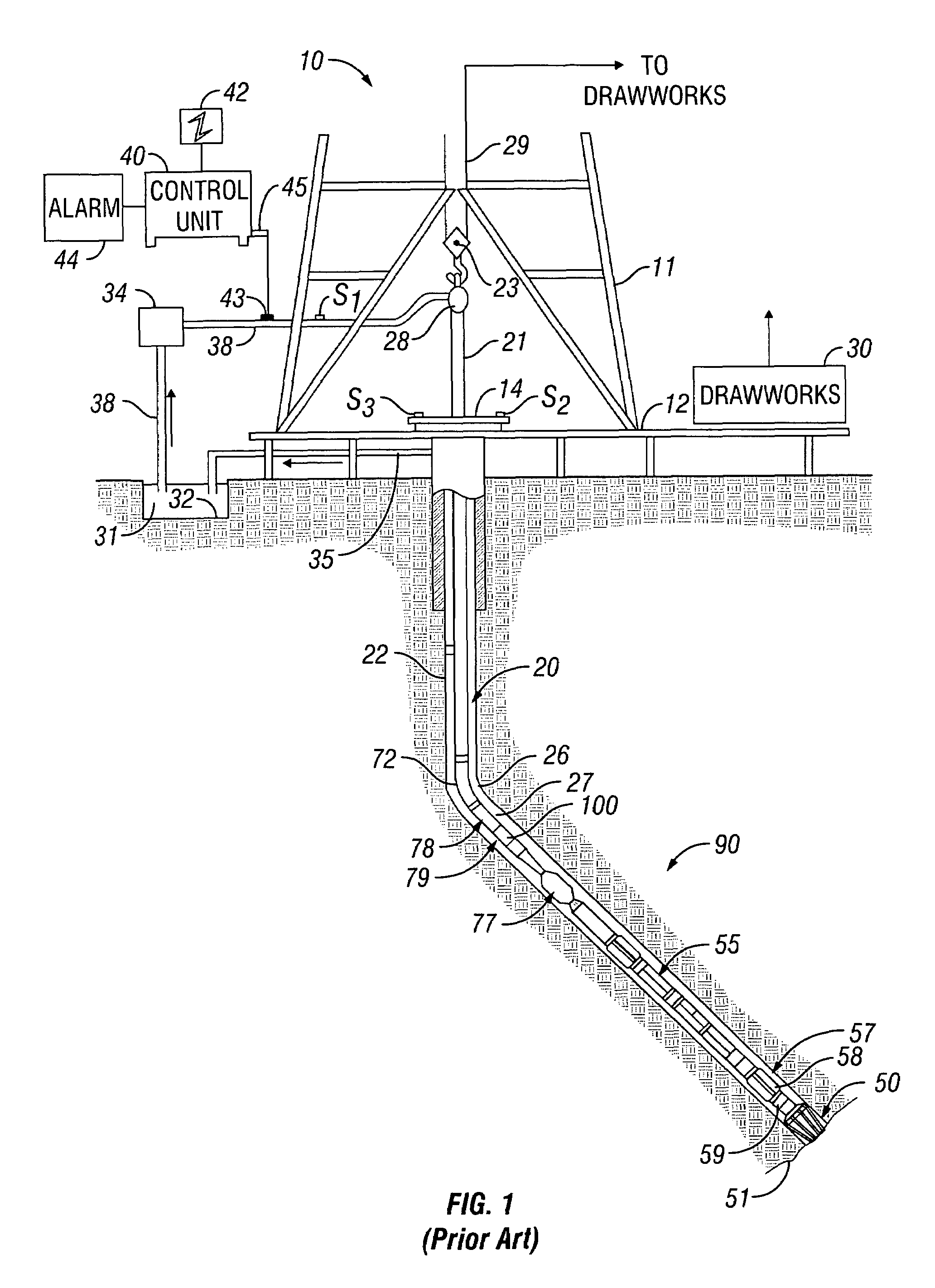
[0031]FIG. 1 shows a schematic diagram of a drilling system 10 with a drillstring 20 carrying a drilling assembly 90 (also referred to as the bottom hole assembly, or “BHA”) conveyed in a “wellbore” or “borehole”26 for drilling the wellbore. The drilling system 10 includes a conventional derrick 11 erected on a floor 12 which supports a rotary table 14 that is rotated by a prime mover such as an electric motor (not shown) at a desired rotational speed. The drillstring 20 includes a tubing such as a drill pipe 22 or a coiled-tubing extending downward from the surface into the borehole 26. The drillstring 20 is pushed into the wellbore 26 when a drill pipe 22 is used as the tubing. For coiled-t...


PUM


Abstract

An induction logging tool having transmitter and receiver antennas is used to make measurements of earth formations. The antennas may be mounted on the mandrel of a bottomhole assembly for MWD applications, or may be pad mounted for wireline applications. The induction measurements are inverted using a linearized model. The model parameters are determined in part from caliper measurements.

Description

CROSS-REFERENCES TO RELATED APPLICATIONS[0001]This application claims priority from U.S. Provisional Patent Application Ser. No. 60 / 637,060 filed on Dec. 17, 2004.BACKGROUND OF THE INVENTION[0002]1. Field of the Invention[0003]The present invention relates to well logging. In particular, the present invention is an apparatus and method for imaging of subsurface formations using electrical methods.[0004]2. Background of the Art[0005]Birdwell (U.S. Pat. No. 3,365,658) teaches the use of a focused electrode for determination of the resistivity of subsurface formations. A survey current is emitted from a central survey electrode into adjacent earth formations. This survey current is focused into a relatively narrow beam of current outwardly from the borehole by use of a focusing current emitted from nearby focusing electrodes located adjacent the survey electrode and on either side thereof. Ajam et al (U.S. Pat. No. 4,122,387) discloses an apparatus wherein simultaneous logs may be made...

Claims


Application Information

Patent Timeline
Patent Type & Authority Patents(United States)
IPC IPC(8): G01V1/38
CPCG01V3/28G01V3/38
Inventor TABAROVSKY, LEONTY A.BESPALOV, ALEXANDREEPOV, MIKHAIL
Owner BAKER HUGHES HLDG LLC
Why Eureka
Try Eureka