Flash storage system with write/erase abort detection mechanism

a technology of write/erase and storage system, applied in the field of nonvolatile memory, can solve the problems of increased hardware design cost, performance gain, and more difficult and costly hardware design, and achieve the effects of reducing system performance penalty, detecting reliably, and reducing performance impa

Active Publication Date: 2007-11-20
SANDISK TECH LLC
View PDF18 Cites 63 Cited by
  • Summary
  • Abstract
  • Description
  • Claims
  • Application Information

AI Technical Summary

Benefits of technology

[0008]According to a first aspect, the present invention presents a non-volatile memory and method for its operation that ensures reliable mechanism for write and erase abort detection in the event of lost of power during non-volatile memory programming and erasing with minimized system performance penalty. In an exemplary embodiment, to ensure a write abort failure can be reliably detected with minimal performance impact, a new write abort detection mechanism is introduced. The algorithm includes a Previous Sector Status flag (PSS) and a Last Sector Status flag (LSS) in the sector overhead information, where the Previous Sector Status flag (PSS) can be protected by ECC.
[0011]In a further aspect of the present invention, an erase abort flag (EAF) in the first sector of the block can be marked after a successful erase operation. With these flags, the system can successful detect a write abort or an erase abort during next initialization of next power on. The write abort detection scheme is especially effective for multi-state memory: (1) it is more difficult and costly to design hardware to handle multi-state systems due to longer programming time required, and (2) the performance gained from not programming twice on every single sector is much greater on multi-state systems also due to longer programming time requirement.

Problems solved by technology

The write abort detection scheme is especially effective for multi-state memory: (1) it is more difficult and costly to design hardware to handle multi-state systems due to longer programming time required, and (2) the performance gained from not programming twice on every single sector is much greater on multi-state systems also due to longer programming time requirement.

Method used


Image

  • Flash storage system with write/erase abort detection mechanism
  • Flash storage system with write/erase abort detection mechanism
  • Flash storage system with write/erase abort detection mechanism

Examples


Embodiment Construction

Example Non-Volatile Memory System

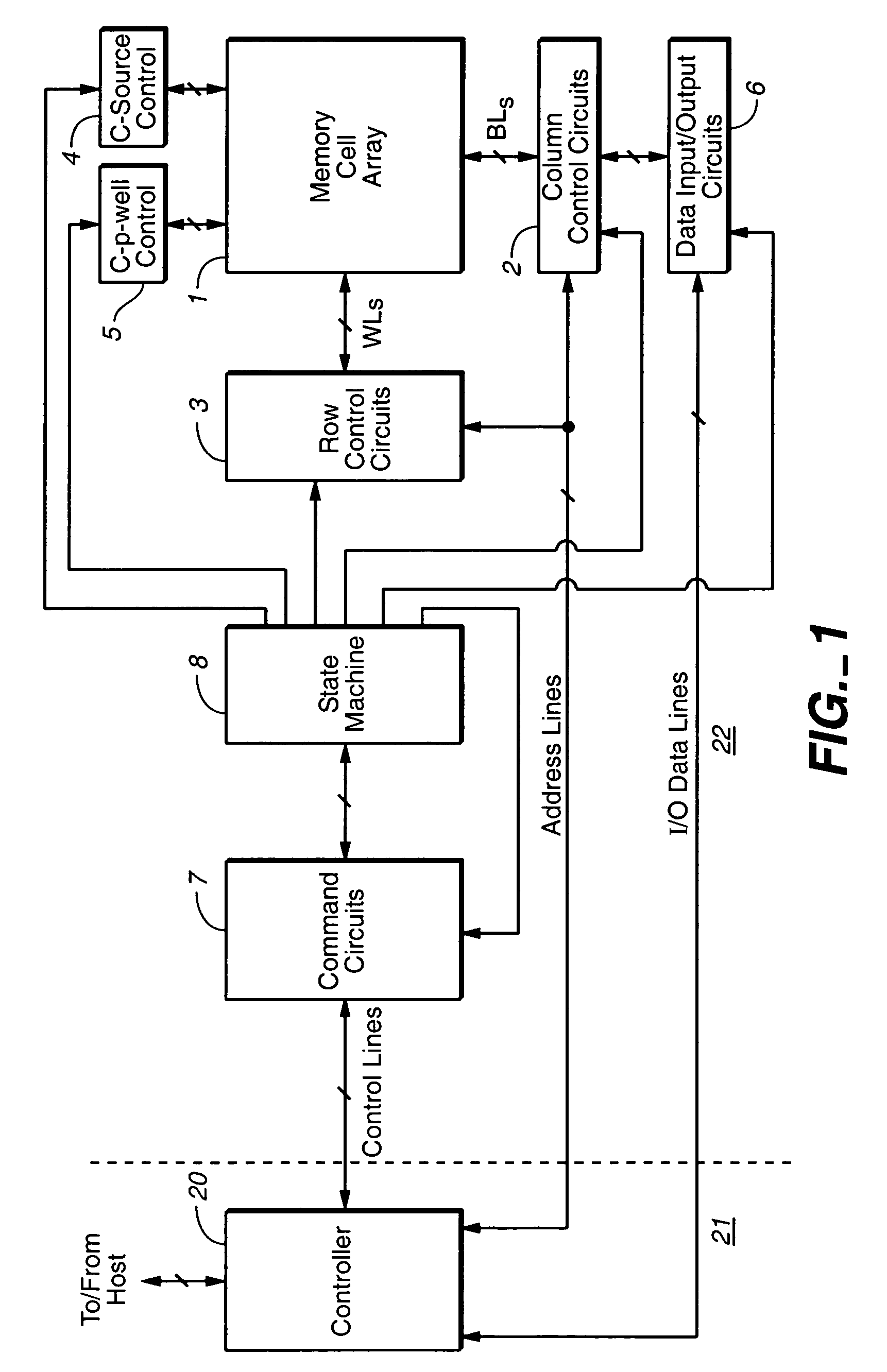
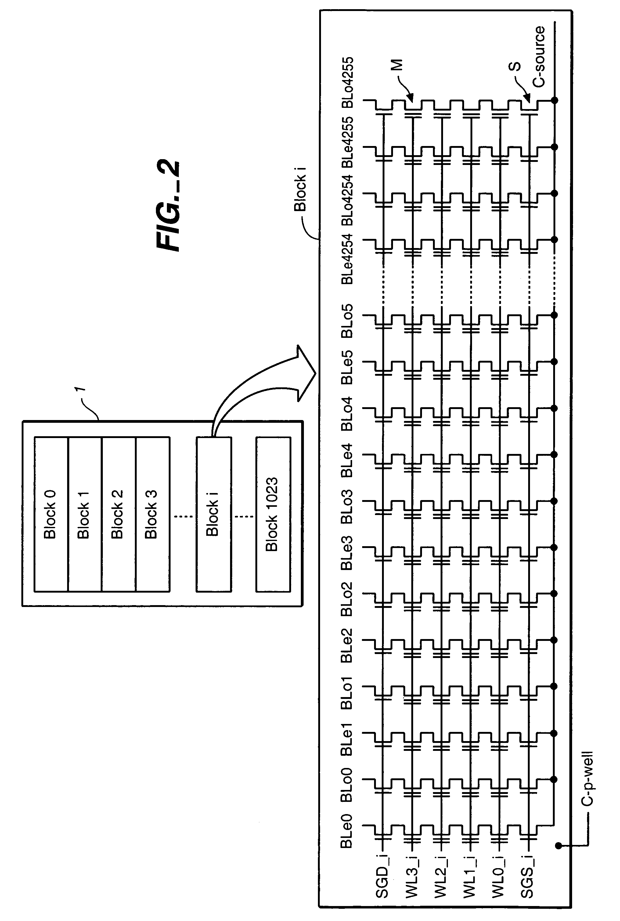
[0020]With reference to FIGS. 1-7, a specific non-volatile memory system is described in which the various aspects of the present invention are implemented, in order to provide specific examples. To reduce the amount of disturb in erase processes, the present invention maintains the control gates of non-selected storage elements at the same voltage level as their underlying well structure. In a exemplary embodiment, the storage elements are formed over a well structure. During an erase process, both the selected and non-selected storage elements over the well are raised to an erase voltage concurrently with establishing this voltage level in the well. This voltage is then held on the well and the non-selected storage elements, thereby reducing the chance of any erase related disturbs, while the selected storage elements are allowed to discharge, producing the needed erase conditions. Further, this can be accomplished without increasing any pitch are...


PUM


Abstract

The present invention presents a non-volatile memory and method for its operation that ensures reliable mechanism for write and erase abort detection in the event of lost of power during non-volatile memory programming and erasing with minimized system performance penalty. During a multi-sector write process, an indication of a successful write in one sector is written into the overhead of the following sector at the same time as the following sector's data content is written. The last sector written will additionally have an indication of its own successful write written into its overhead. For erase, an erase abort flag in the first sector of the block can be marked after a successful erase operation.

Description

FIELD OF THE INVENTION[0001]This invention relates generally to a non-volatile memory and its operation, and, more specifically, to determining aborted write and erase operations.BACKGROUND OF THE INVENTION[0002]A common application of flash EEPROM devices is as a mass data storage subsystem for electronic devices. Such subsystems are commonly implemented as either removable memory cards that can be inserted into multiple host systems or as non-removable embedded storage within the host system. In both implementations, the subsystem includes one or more flash devices and often a subsystem controller.[0003]Flash EEPROM devices are composed of one or more arrays of transistor cells, each cell capable of non-volatile storage of one or more bits of data. Thus flash memory does not require power to retain the data programmed therein. Once programmed however, a cell must be erased before it can be reprogrammed with a new data value. These arrays of cells are partitioned into groups to pro...

Claims


Application Information

Patent Timeline
Patent Type & Authority Patents(United States)
IPC IPC(8): G06F12/00G11C16/04G11C16/10
CPCG11C16/0416G11C16/105G11C16/10G11C2216/16G11C16/16G11C16/26G11C16/3454G11C2211/5646
Inventor LIN, JASONCONLEY, KEVIN M.CHANG, ROBERT C.
Owner SANDISK TECH LLC
Why Eureka
Try Eureka