
Process and device for determining the internal temperature of a catalytic converter of a vehicle equipped with a heat engine

a technology of heat engine and internal temperature, which is applied in the direction of machines/engines, electric control, instruments, etc., can solve the problems of difficult environment for a probe, difficult installation of a heat probe inside the catalytic converter, and inability to determine the temperature of this material, so as to reduce the complexity and the cost of the device

Inactive Publication Date: 2007-11-27
PEZHO SITROEN AUTOMOBILS SA
View PDF21 Cites 4 Cited by
  • Summary
  • Abstract
  • Description
  • Claims
  • Application Information

AI Technical Summary

Benefits of technology

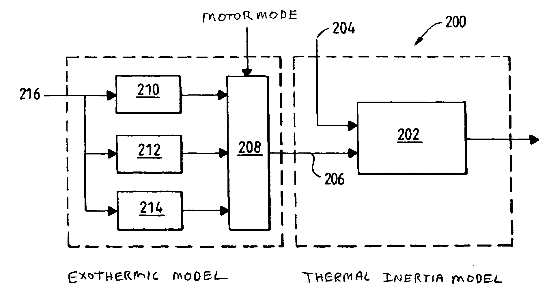
[0018]Thus, the phenomenon of inertia of the catalytic converter is reproduced by means of a simple operation requiring rather inexpensive calculation elements.
[0019]By weighting each measurement by a variable that is a function of the oxidation activity of the catalytic converter, the exothermic phenomenon of the catalytic converter is simulated as was described above in just as simple and rather inexpensive a manner.
[0020]In addition, the process according to the present invention has the advantage of not requiring a temperature probe inside the catalytic converter, which reduces the complexity and the cost of the device for determining the temperature in the catalytic converter.
[0026]Thus, using a simple formula, it is possible to determine the internal temperature of the catalytic converter by simulating the two thermal phenomena, which practically regulate the temperature of the catalytic converter.

Problems solved by technology

However, if such a turbocompressor is not present, the catalytic converter receives the exhaust gases of the engine directly.
However, the determination of the temperature of this material is problematic given that it reaches elevated temperatures making the environment difficult for a probe.
In addition, the installation of a heat probe inside the catalytic converter is complicated and expensive.

Method used


Image

  • Process and device for determining the internal temperature of a catalytic converter of a vehicle equipped with a heat engine
  • Process and device for determining the internal temperature of a catalytic converter of a vehicle equipped with a heat engine
  • Process and device for determining the internal temperature of a catalytic converter of a vehicle equipped with a heat engine

Examples


Embodiment Construction

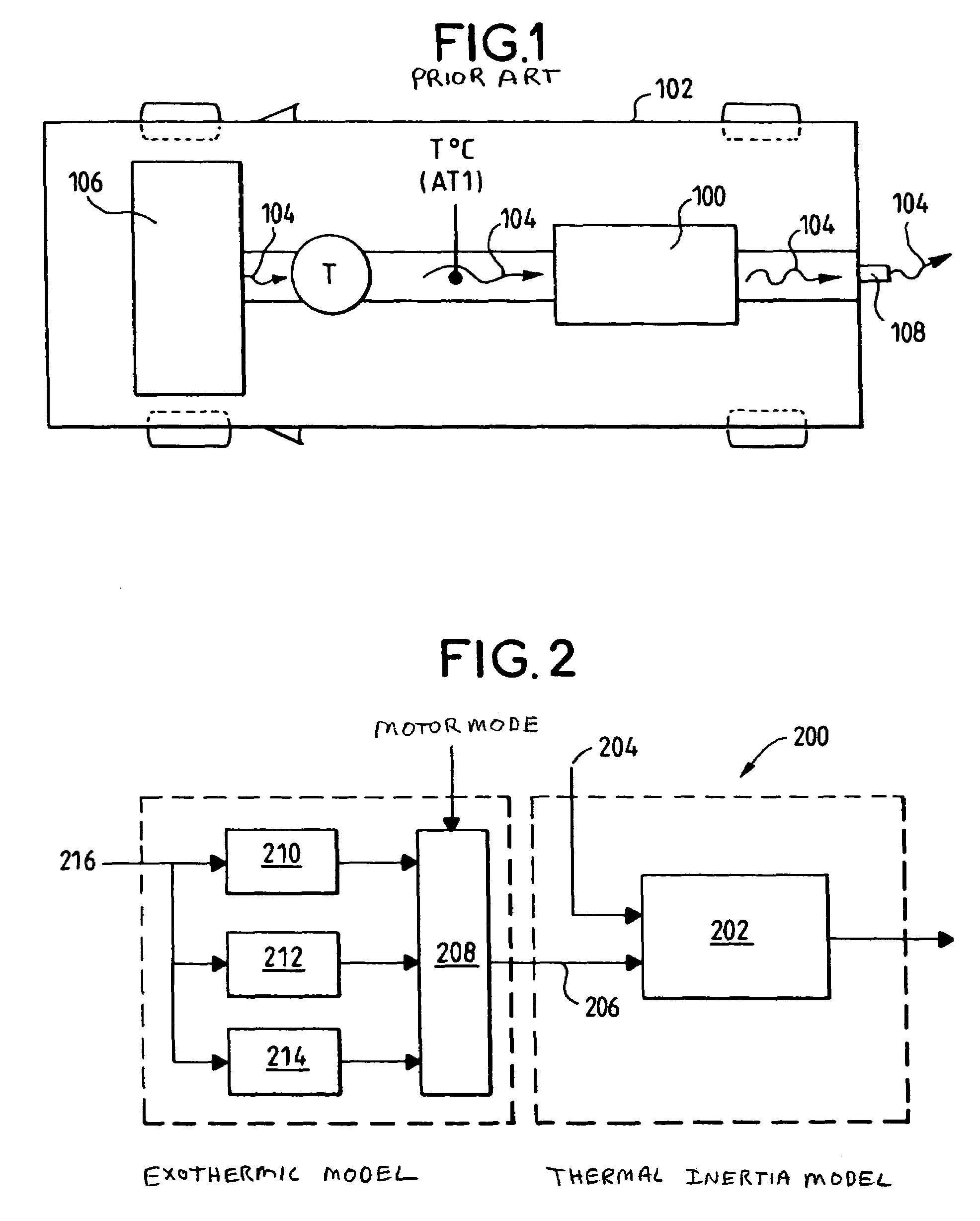
[0033]In the above-described embodiment of the present invention, the process according to the present invention is carried out in a processor 200, which comprises for this purpose the means 202 determining the mean value of the engine exhaust gas temperature measurements 204, these measurements being carried out before the admission of these gases into the catalytic converter over a limited period of time, such that when a new temperature measurement is taken into account, the oldest temperature measurement is not taken into account in the calculation of the mean value any longer.

[0034]Thus, taking into account that the temperature of the catalytic converter can be obtained by calculating such a sliding mean value, the phenomenon of thermal inertia of the catalytic converter during the heating of the said catalytic converter by the exhaust gases is simulated.

[0035]Thus, the calculation of such a mean value, also called a sliding mean value, causes the catalytic converter temperatur...


PUM


Abstract

The present invention pertains to a process for determining the internal temperature of a catalytic converter of a vehicle equipped with a heat engine. According to the present invention, such a process is characterized in that this temperature is determined by calculating the mean value of exhaust gas temperature measurements carried out before the admission of these gases into the catalytic converter over a limited period of time, these measurements being weighted by a variable that is a function of the oxidation activity of the catalytic converter.

Description

FIELD OF THE INVENTION[0001]The present invention pertains to a process and a device for determining the internal temperature of a catalytic converter of a vehicle equipped with a heat engine.BACKGROUND[0002]The catalytic converter 100 (FIG. 1) is used in a vehicle 102 to improve the quality of the exhaust gases 104 discharged from the engine 106 of the said vehicle.[0003]To achieve this, the said catalytic converter 100 receives the gases 104 discharged by the engine 106 of the vehicle 102 in order to treat them by means, in particular, nitrogen oxide (NOx) traps or particle filters intended to remove the latter.[0004]In certain cases, as is shown in FIG. 1, the said catalytic converter 100 may be located at the outlet of a turbocompressor T with which the said vehicle 102 is equipped if the vehicle is equipped with such a turbocompressor.[0005]However, if such a turbocompressor is not present, the catalytic converter receives the exhaust gases of the engine directly.[0006]Conseque...

Claims


Application Information

Patent Timeline
Patent Type & Authority Patents(United States)
IPC IPC(8): G01M19/00G01M99/00F01N9/00F01N11/00F02D41/02F02D41/14
CPCF01N9/005F01N11/005F02D41/1446F01N2550/02Y02T10/47F02D2200/0804F02D41/0235Y02T10/40
Inventor AUDOIN, ARNAUD
Owner PEZHO SITROEN AUTOMOBILS SA
Learn More