Chisel holder

a technology of holder and chisel, which is applied in the direction of cutting machines, earthwork drilling and mining, slitting machines, etc., can solve the problems of changing the power consumption of the machine, and achieve the effect of good chip-breaking geometry

Active Publication Date: 2007-11-27
WIRTGEN GMBH
View PDF14 Cites 60 Cited by
  • Summary
  • Abstract
  • Description
  • Claims
  • Application Information

AI Technical Summary

Benefits of technology

[0007]It is one object of this invention to provide a chisel holder of the type mentioned above but in which the cutting output of a road milling cutter or the like can be improved.
[0009]It is possible with the chip breaker to effectively cut up the created chips, in particular larger clods. The cutting resistance which the chisel holder offers the milled material is thus reduced, which results in a reduction of the power consumption.
[0010]An improvement of the machine efficiency can thus be obtained.
[0011]A connection of the holding neck with the protrusion by the connecting section results in an improved tool stiffness. This has a positive effect, in particular in connection with exposed holding necks and / or protrusions, and leads to an increase in the tool life.
[0012]In accordance with one embodiment of this invention, the connecting section extends in the tool advancement direction. A cutting geometry is thus created which offers a low penetration resistance to the milled material.
[0017]An optimization of the cutting geometry of the chisel holders results if the base element is laterally delimited by two inclined faces in the area of or near the protrusion, which are arranged in an arrow shape with respect to each other in the tool advancement direction. The connecting section and the inclined faces terminate in a frontal end section of the protrusion. The frontal end section forms a tapered section which makes possible a good chip removal, in particular in connection with rough-chipped milling bases.

Problems solved by technology

The power consumption of the machine changes as a function of the nature of the ground to be worked.

Method used


Image

  • Chisel holder
  • Chisel holder
  • Chisel holder

Examples


Embodiment Construction

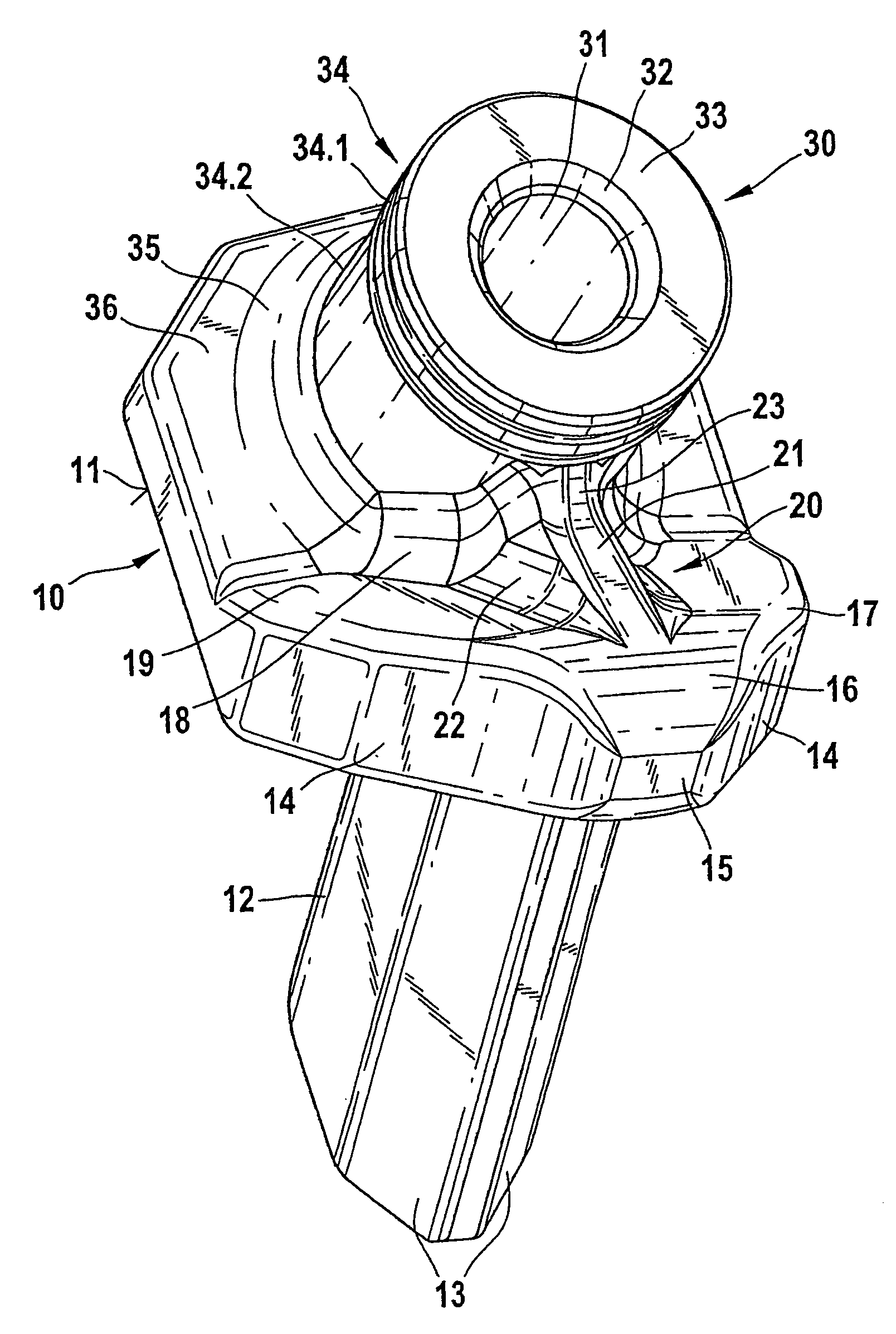
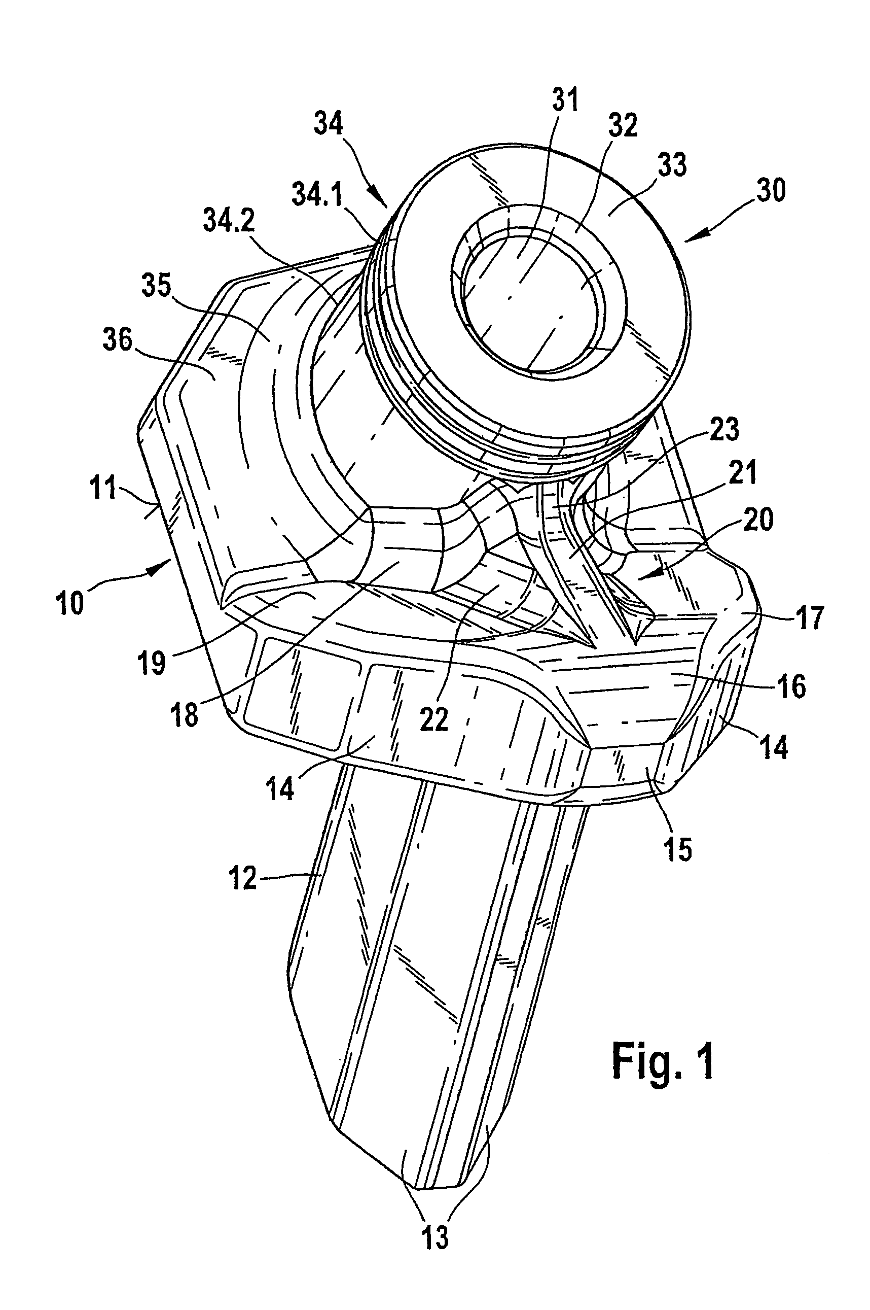
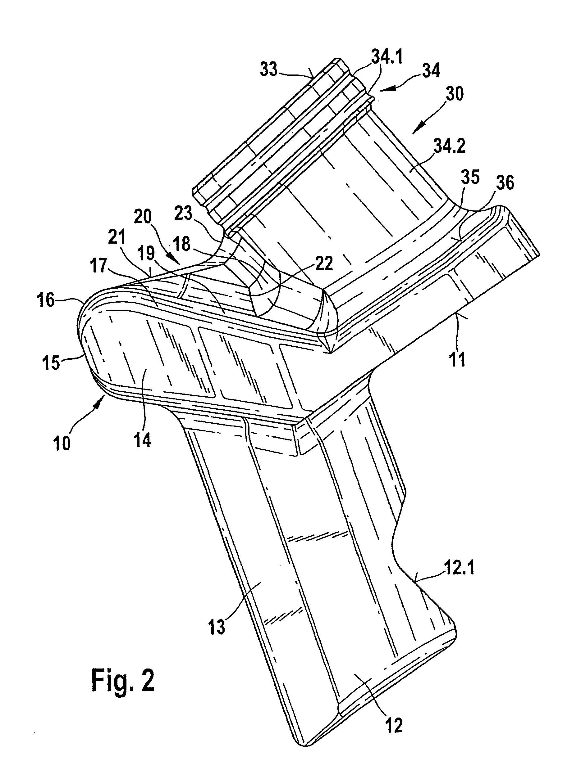
[0024]FIG. 1 shows a chisel holder with a base element 10. The base element 10 has a support section with a downward-oriented support surface 11. In an advancement direction the support element makes a transition into a protrusion 15. In this case, the protrusion 15 is arranged at an angle with respect to the support element.

[0025]A downward protruding plug-in neck 12 is formed on the base element 10 in the transition area from the support element to the protrusion 15. The chisel holder can be inserted by the plug-in neck 12 into a plug-in receiver of a base body 50. Then the plug-in neck 12 can be fixed in place in the plug-in receiver by clamping.

[0026]Here, centering faces 13 at the front, as well as a rear clamping face 12.1 of the plug-in neck 12, shown in FIG. 2, are used as a support. In the assembled state, the chisel holder is supported by its support surface 11 on an opposite surface of the base body 50. The protrusion 15 covers a shoulder 51 of the base body 50 and thus p...


PUM


Abstract

A chisel holder for a road milling machine or the like, having a base element which supports a holding neck, wherein the holding neck has a chisel receiver and a protrusion is connected to the base element upstream of the holding neck when viewed in an advancing direction of the tool. For improving the cutting output, in particular in connection with rough-chipped milling materials, the base element has a connecting section designed as a chip breaker, which is formed on the base element and extends, starting at the holding neck, at least partially over the protrusion.

Description

BACKGROUND OF THE INVENTION[0001]1. Field of the Invention[0002]This invention relates to a chisel holder for a road milling machine or the like, having a base element which supports a holding neck, wherein the holding neck has a chisel receiver and a protrusion is connected to the base element upstream of the holding neck when viewed in an advancing direction of the tool.[0003]2. Discussion of Related Art[0004]A chisel holder is known from German Patent Reference DE 43 22 401 C2 (U.S. Pat. No. 5,683,144). The known chisel holder has a plug-in neck, by which it is exchangeably held in a plug-in receiver of a base body. The base body is fastened on an outer circumference of a milling roller tube. The plug-in neck of the chisel holder is connected in one piece to a base element. On a side facing away from the plug-in neck, the base element has a holding neck. The holding neck has a bore into which a shank chisel can be inserted in a known manner. By way of example, German Patent Refer...

Claims


Application Information

Patent Timeline
Patent Type & Authority Patents(United States)
IPC IPC(8): E21C35/18
CPCE21C35/18
Inventor HOLL, BERNDTEWES, GUNTER
Owner WIRTGEN GMBH
Why Eureka
Try Eureka