Industrial robot

a robot and industrial technology, applied in the field of industrial robots, can solve the problems of very limited work space and achieve the effect of reducing the demand for control accuracy

Active Publication Date: 2007-11-27
ABB (SCHWEIZ) AG
View PDF3 Cites 47 Cited by
  • Summary
  • Abstract
  • Description
  • Claims
  • Application Information

AI Technical Summary

Benefits of technology

[0021]According to an embodiment of the invention the distance between the inner joint of the first link, and the inner joint of the second link is shorter than the distance between the outer joint of the first link and the outer joint of the second link. The forces on the link arrangement decrease as the distance between the outer joints increases. Thus, this embodiment reduces the forces on the links of the first arm.
[0041]According to an embodiment of the invention, the movements of at least one of the first and second arm are controlled by a compliant servo control during passage of the third position of the robot. Thus, the demand on the accuracy of the control is reduced during passage through the singular position.

Problems solved by technology

In particular, the workspace is very limited compare to the total space occupied by the robot including the linear paths.

Method used


Image

  • Industrial robot
  • Industrial robot
  • Industrial robot

Examples


Embodiment Construction

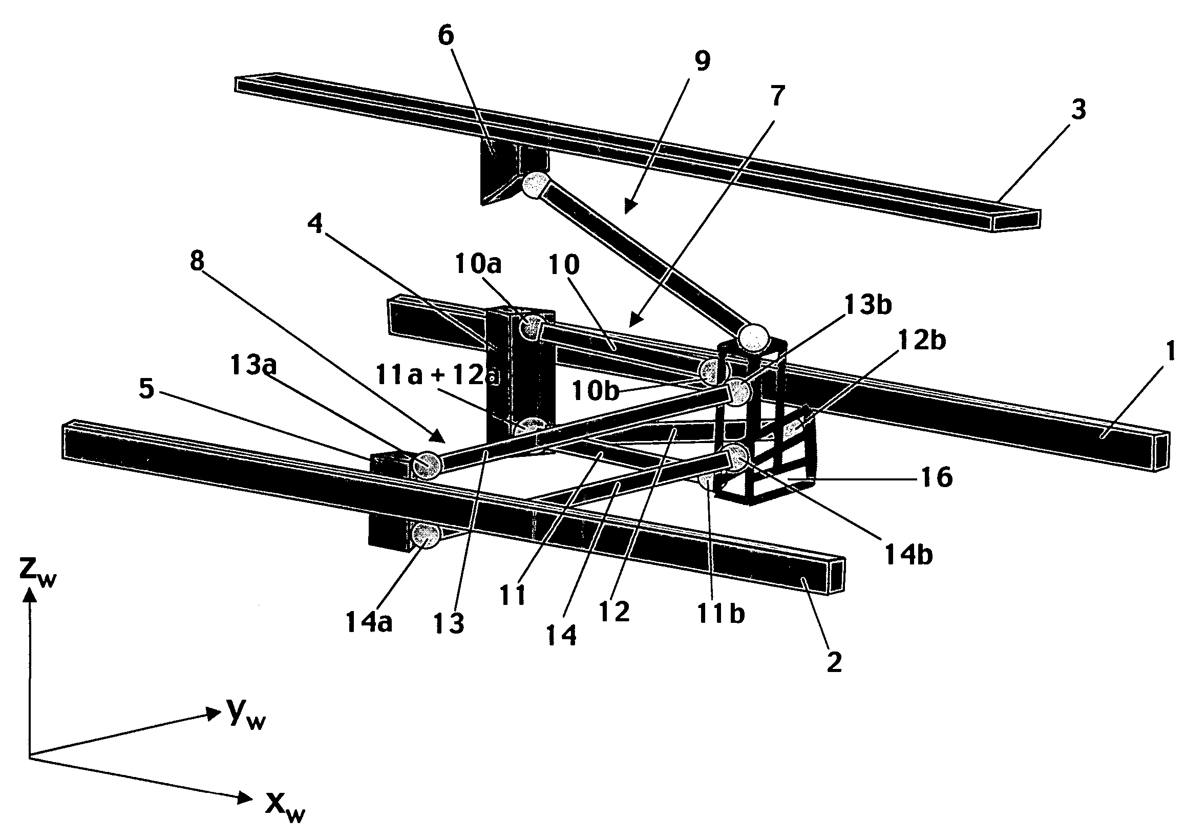
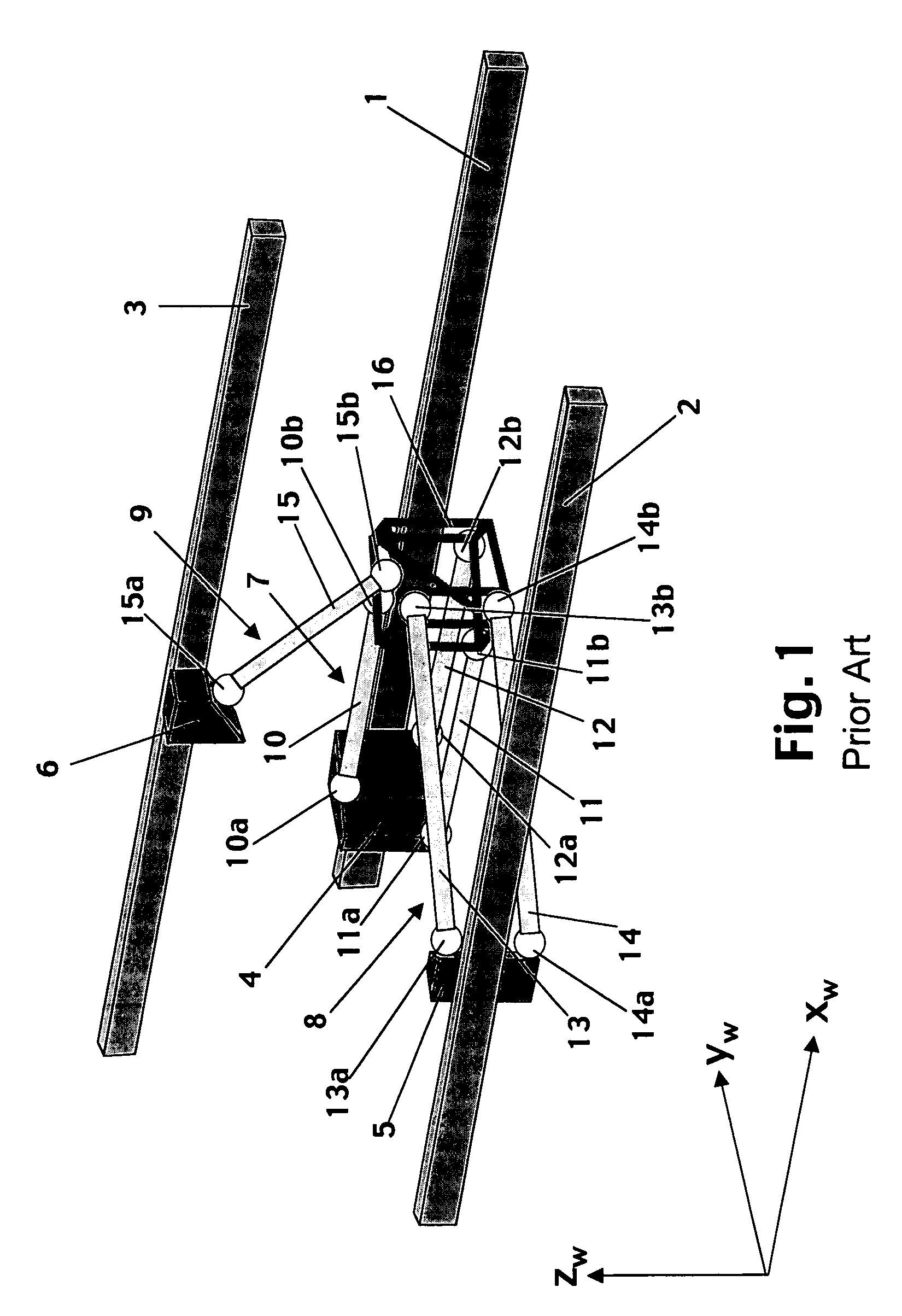
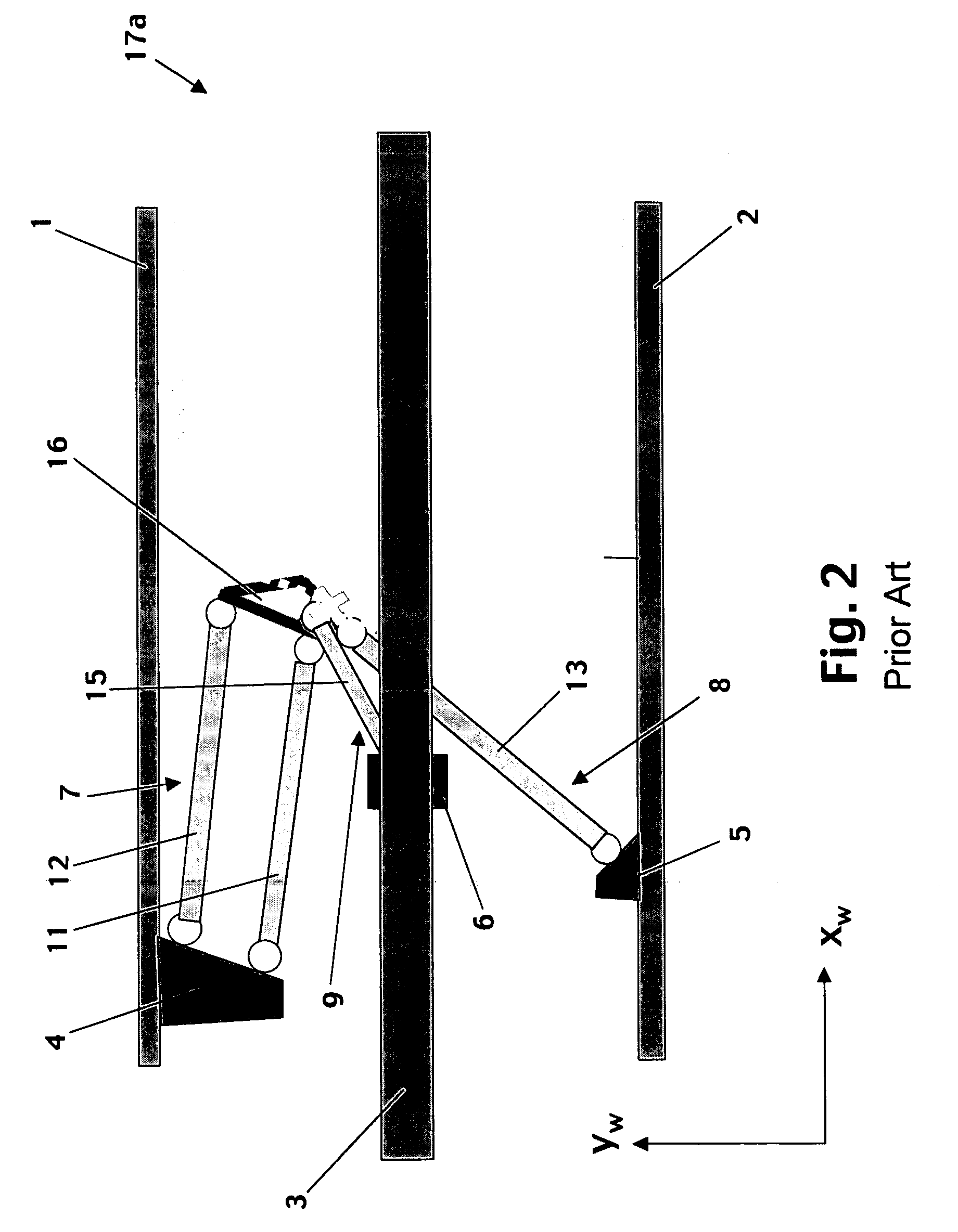
[0067]FIG. 1 shows a prior art design of a gantry type of parallel kinematic manipulator (PKM) having a rather big workspace, but which cannot make a full reconfiguration to work in both directions between the linear paths. The PKM includes two paths 1 and 2, which together define a plane parallel to the xwyw-plane of the world coordinate system shown in the figure. On path 1 there is a carriage 4, which is actuated to move along path 1 by for example a motor-driven ball screw linear module, a motor-driven band transmission, a rack-and pinion drive, or a direct-driven linear motor. In the same way a carriage 5 is actuated along a path 2, and a carriage 6 along a path 3. The path 6 is parallel with the paths 1 and 2 and forms a triangular geometry in the ywzw-plane together with the paths 1 and 2. Each carriage is connected to an actuated platform 16 by means of an arm, the carriage 4 with a first arm 7, the carriage 5 with a second arm 8 and the carriage 6 with a third arm 9. The fi...


PUM


Abstract

An industrial robot including a platform arranged for carrying an object. A first arm is arranged for influencing the platform in a first movement and includes a first actuator having a first path and a first carriage linearly movable along the first path. A second arm is arranged for influencing the platform in a second movement, and includes a second actuator having a second path and a second carriage linearly movable along the first path. A third arm is arranged for influencing the platform in a third movement. A control unit controls the movements of the platform. The first and second arms are arranged rotatable in such way that the platform is movable between opposite sides of a second plane passing through and continuously following the first and second carriage. The control unit includes a control adapted to upon command perform a reconfiguration of the platform and the arms of the robot. The reconfiguration includes moving the platform between opposite sides of the second plane.

Description

CROSS-REFERENCE TO RELATED APPLICATIONS [0001]This application claims priority to U.S. provisional patent application 60 / 529,695 filed 16 Dec. 2003, U.S. provisional patent application 60 / 536,506 filed 15 Jan. 2004, and U.S. provisional patent application 60 / 578,322 10 Jun. 2004.FIELD OF THE INVENTION[0002]The present invention relates to an industrial robot. Such a robot includes a manipulator and control equipment for moving an object in space. The manipulator includes a parallel kinematic manipulator including at least three arms, each including a link arrangement. The manipulator includes a platform jointly supported by the three arms. Each arm is associated with an actuator with the purpose of moving the links of the arm such that a movement of the platform is attained. The task of the platform is to directly or indirectly support tools or objects, large as well as small, for movement, measurement, processing, working, joining, etc. In particular, the manipulator is intended to...

Claims


Application Information

Patent Timeline
Patent Type & Authority Patents(United States)
IPC IPC(8): B25J5/00B25J9/02B25J9/06B25J17/02B66C23/00
CPCB25J17/0266B25J9/0072Y10T74/20305Y10T74/20335
Inventor BROGARDH, TORGNY
Owner ABB (SCHWEIZ) AG
Why Eureka
Try Eureka