
Printed wiring boards possessing regions with different coefficients of thermal expansion

a technology of thermal expansion and printed wiring, which is applied in the association of printed circuit non-printed electrical components, electrical apparatus construction details, coupling device connections, etc., and can solve problems such as the separation of electronic devices

Inactive Publication Date: 2007-11-27
STABLCOR TECH
View PDF40 Cites 57 Cited by
  • Summary
  • Abstract
  • Description
  • Claims
  • Application Information

AI Technical Summary

Problems solved by technology

If mismatches occur, then thermal cycling can cause the electronic device to separate from the printed wiring board.

Method used


Image

  • Printed wiring boards possessing regions with different coefficients of thermal expansion
  • Printed wiring boards possessing regions with different coefficients of thermal expansion
  • Printed wiring boards possessing regions with different coefficients of thermal expansion

Examples


Embodiment Construction

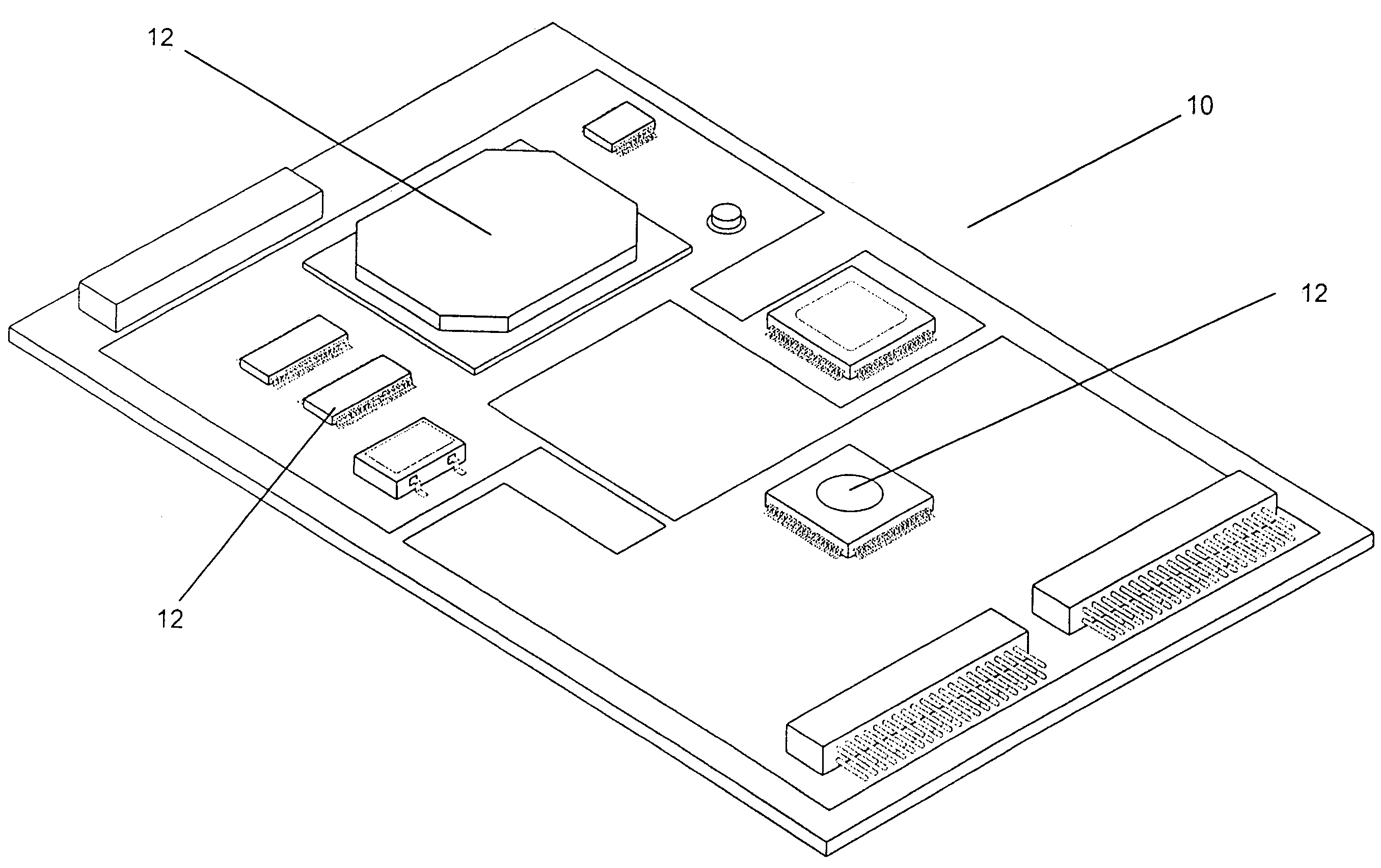
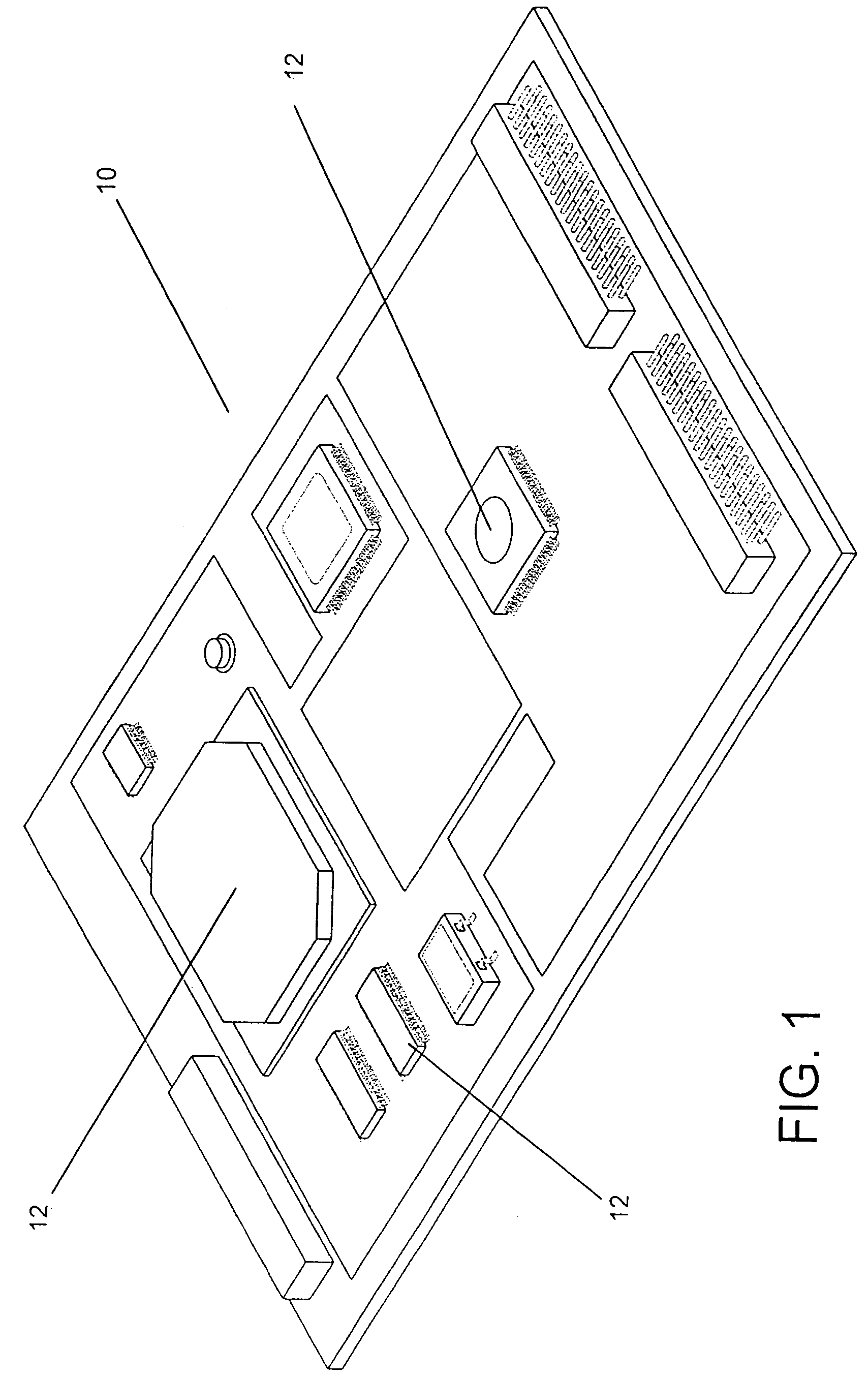
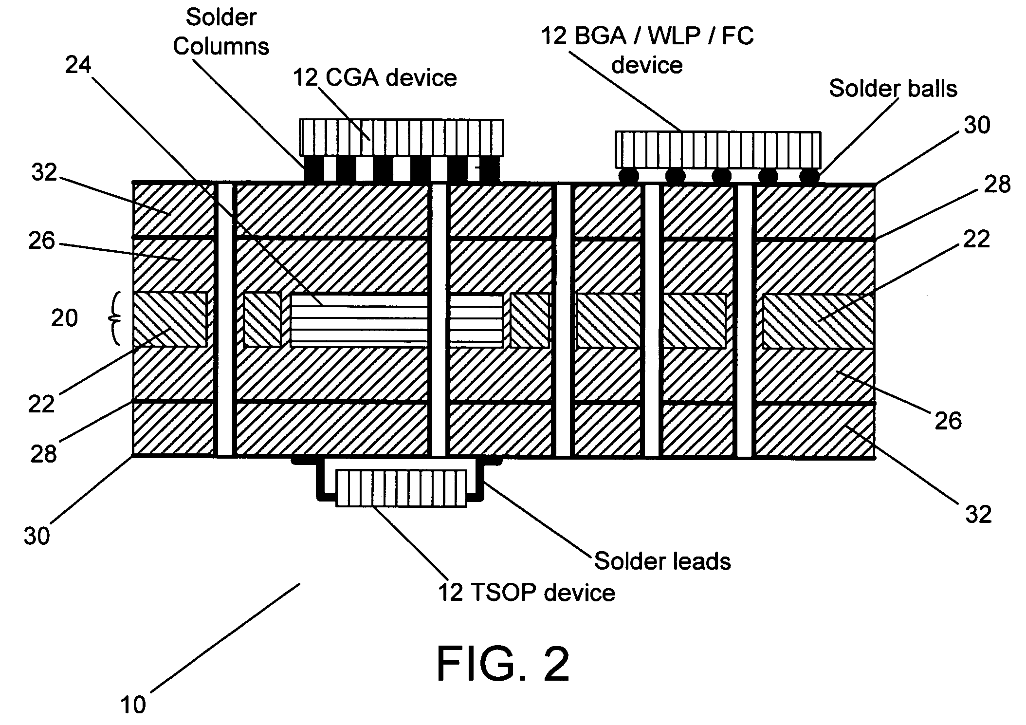
[0052]Turning now to the drawings, printed wiring boards including localized regions having different physical properties (such as CTE) are illustrated. Printed wiring boards in accordance with the present invention can be manufactured by taking a layer of base material possessing a first set of physical properties, removing a portion of that base material and inserting an insert material having a second set of physical properties where the portion of base material has been removed. The layer of base material and the insert material can then be combined using a resin capable of absorbing the various forces created in instances where the two materials expand and contract at different rates. In many embodiments, multiple insert materials possessing various physical properties are combined with a base material. In one embodiment, the insert materials can each possess a CTE that differs from that of the base material. Alternatively, at least one of the insert materials can have the same...


PUM

PropertyMeasurementUnit
distanceaaaaaaaaaa
electrically conductiveaaaaaaaaaa
dielectricaaaaaaaaaa

Abstract

Printed wiring boards are disclosed that include regions having different coefficients of thermal expansion. In one aspect of the invention, the regions can be matched to the coefficients of thermal expansion of devices mounted on the printed wiring board. In one embodiment, the invention includes a layer including a base material and at least one insert material that are combined using a resin. In addition, the base material and insert material are located within the same plane.

Description

CROSS-REFERENCE TO RELATED APPLICATIONS[0001]This application claims the benefit of U.S. Provisional Patent Application Ser. No. 60 / 604,857 filed Aug. 27, 2004, the disclosure of which is incorporated herein by reference in its entirety.BACKGROUND[0002]The present invention generally relates to printed wiring boards and more specifically to printed wiring boards having localized regions with different coefficients of thermal expansion (CTEs).[0003]Printed wiring boards can be used to establish electrical connections between devices. In some instances, the devices can be mounted on the printed wiring board. The manner in which the devices are mounted is typically dependent upon the packaging of the device. Examples of packages used for electronic devices include Dual Inline Packages, Small Outline Packages, Thin Small Outline Packages (TSOP), Plastic Packages, Leadless Ceramic Chip Carriers, Ceramic Packages, Ball Grid Array Packages (BGA), Pin Grid Arrays (PGA), Pad Array Carriers (...

Claims


Application Information

Patent Timeline
Patent Type & Authority Patents(United States)
IPC IPC(8): H05K1/03H05K1/00H05K1/18H05K7/00
CPCH05K1/0271H05K3/4641H05K3/4694H05K1/0366H05K3/429H05K3/4626H05K2203/063H05K2201/0187H05K2201/0209H05K2201/0323H05K2201/068H05K2201/10416
Inventor VASOYA, KALU K.
Owner STABLCOR TECH
Learn More