Hand lamp, especially for magnetic crack detection

a technology for crack detection and hand lamps, which is applied in the field of hand lamps, can solve problems such as danger to the skin of the operator, and achieve the effects of reducing the intensity of leds, ensuring safety, and optimum light yield

Inactive Publication Date: 2007-11-27
ILLINOIS TOOL WORKS INC
View PDF11 Cites 13 Cited by
  • Summary
  • Abstract
  • Description
  • Claims
  • Application Information

AI Technical Summary

Benefits of technology

[0011]Light generation in a LED hand lamp takes place in the LED directly by changing the path of the electrons in a semiconductor crystal. Based on this fact, light radiation only occurs in the wavelength range which corresponds to the quanta emitted when the path of the electrons changes. In contrast, thermal radiators such as conventional UV lamps, emit continuously in a very wide spectral range, which is unnecessary or harmful for crack detection and must be filtered out in the known UV lamps. Especially UVB and UVC radiation which is toxic and which occurs in classic UV lamps can be eliminated by the LED in accordance with the invention as the illuminant. The formation of harmful radiation in the shortwave UV range which is damaging to the ocular fundus and dangerous to the skin of the operator, since this radiation causes “sunburn” or radiation damage, is thus eliminated.
[0022]Thus, among others the following advantages are achieved by the hand lamp in accordance with the invention:

Problems solved by technology

In contrast, thermal radiators such as conventional UV lamps, emit continuously in a very wide spectral range, which is unnecessary or harmful for crack detection and must be filtered out in the known UV lamps.
The formation of harmful radiation in the shortwave UV range which is damaging to the ocular fundus and dangerous to the skin of the operator, since this radiation causes “sunburn” or radiation damage, is thus eliminated.

Method used


Image

  • Hand lamp, especially for magnetic crack detection
  • Hand lamp, especially for magnetic crack detection

Examples


Embodiment Construction

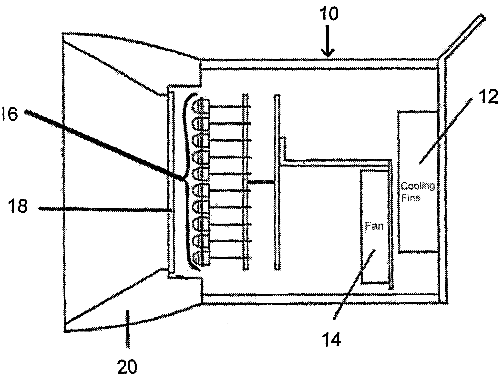
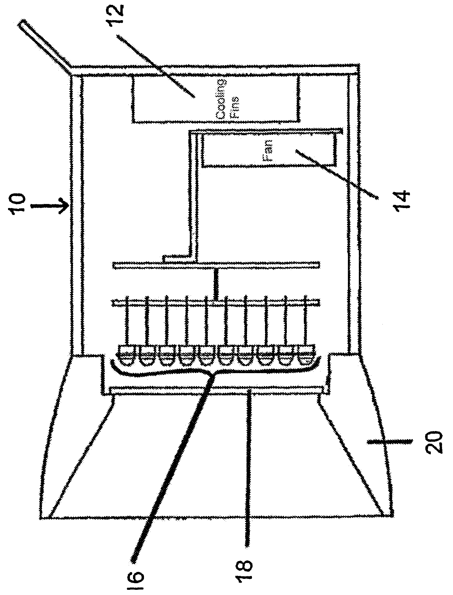
[0032]As is apparent from the FIG., the hand lamp has a housing 10 with a rib cooling body 12 and a fan 14. Both are used for cooling the LEDs 16 which are located in a radiation field, and as shown, are mounted to a common plate structure the fan within a lamp housing with the rib cooling body being mounted to an end wall of the lamp housing. In front of the radiation field there is a protective pane 18 and a frame for the pane which protects the latter. Cool air from the area of the rib cooling body is routed in the direction of the LED and in the lamp by operation of the fan and thus cooling and prevention of local heating are achieved.

[0033]Preferably the housing is splash-proof, therefore leak-proof, and satisfies standard IP65. The lamp furthermore has a control such as a microprocessor which monitors by way of temperature sensors whether a threshold temperature has been exceeded and accordingly controls the power supply to the LEDs. In this way it can be ensured that heat gen...


PUM

PropertyMeasurementUnit
DC voltageaaaaaaaaaa
weightaaaaaaaaaa

Abstract

The invention relates to a manual lamp, especially for optical crack testing according to the magnetic powder testing and dye penetration method. Said manual lamp comprises at least one LED having an emission wavelength located in the UVA range as an illuminating means.

Description

BACKGROUND OF THE INVENTION [0001]1. Filed of Invention[0002]The invention relates to a hand lamp especially for magnetic crack detection and using the dye penetration process.[0003]2. Description of Related Art[0004]Hand lamps for crack detection are known. They are used for flaw detection in optical crack detection using the dye penetration process and magnetic crack detection to reveal the concentration of fluorescent particles in cracks in a higher concentration of dye particles by their fluorescence and thus for determining cracks. As the technical background, German Patent Application DE 19639020 A1 is mentioned, in which a generic dye penetration process is explained, the use of the hand lamp in accordance with the invention in no way being limited to this application. Typical applications of hand lamps are especially the checking of poorly accessible cavities like the inside walls of pipes, surfaces which are not illuminated in incident light—in general, areas which can be p...

Claims


Application Information

Patent Timeline
Patent Type & Authority Patents(United States)
IPC IPC(8): G01R31/00F21L4/02F21V29/00G01N27/84G01N21/91
CPCG01N27/84G01N21/91
Inventor ANNIGHOEFER, ROLFTOMASCHKO, SIGMARVETTERLEIN, THOMAS
Owner ILLINOIS TOOL WORKS INC
Why Eureka
Try Eureka