Flexible waveguide cable with a dielectric core

Inactive Publication Date: 2007-11-27
INTEL CORP
View PDF16 Cites 268 Cited by
  • Summary
  • Abstract
  • Description
  • Claims
  • Application Information

AI Technical Summary

Benefits of technology

[0024]As can be seen by plot 720, the waveguide filter is associated with two high frequency pass-band regions 730, 740. Note that the region 750 between the two high frequency pass-band regions 730, 740 might be caused by, for example, interference from another mode. According to some embodiments, a multi-band modulated carrier may be used to transmit digital information using the frequencies of the pass-band regions 730, 740. Note that as the diameter of a dielectric core becomes smaller, the frequencies associated with the pass-band regions may increase. Acc

Problems solved by technology

As the rate at which digital information is being transmitted increases, energy losses associated with the cable 150 may also increase.
As a result, the rate at which digital inf

Method used


Image

  • Flexible waveguide cable with a dielectric core
  • Flexible waveguide cable with a dielectric core
  • Flexible waveguide cable with a dielectric core

Examples


Example

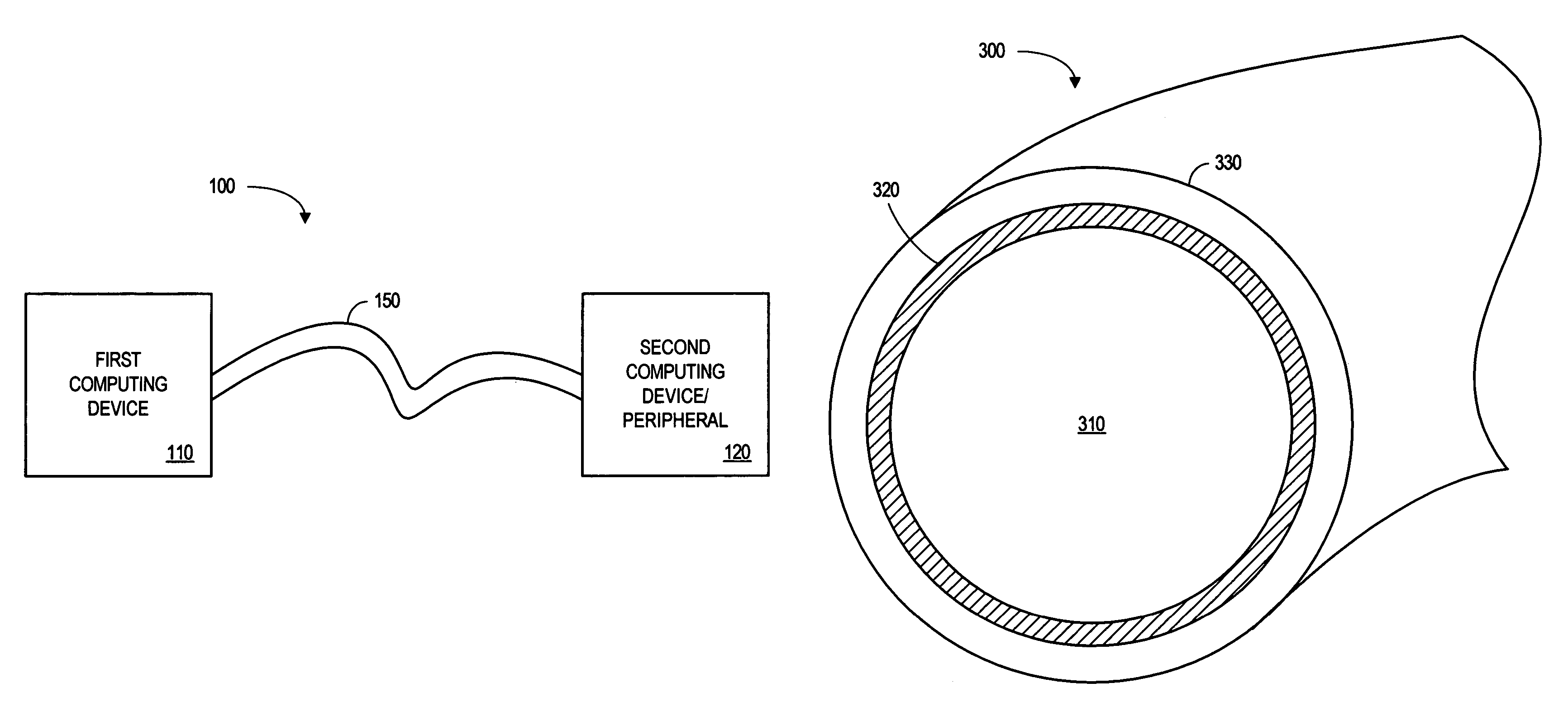
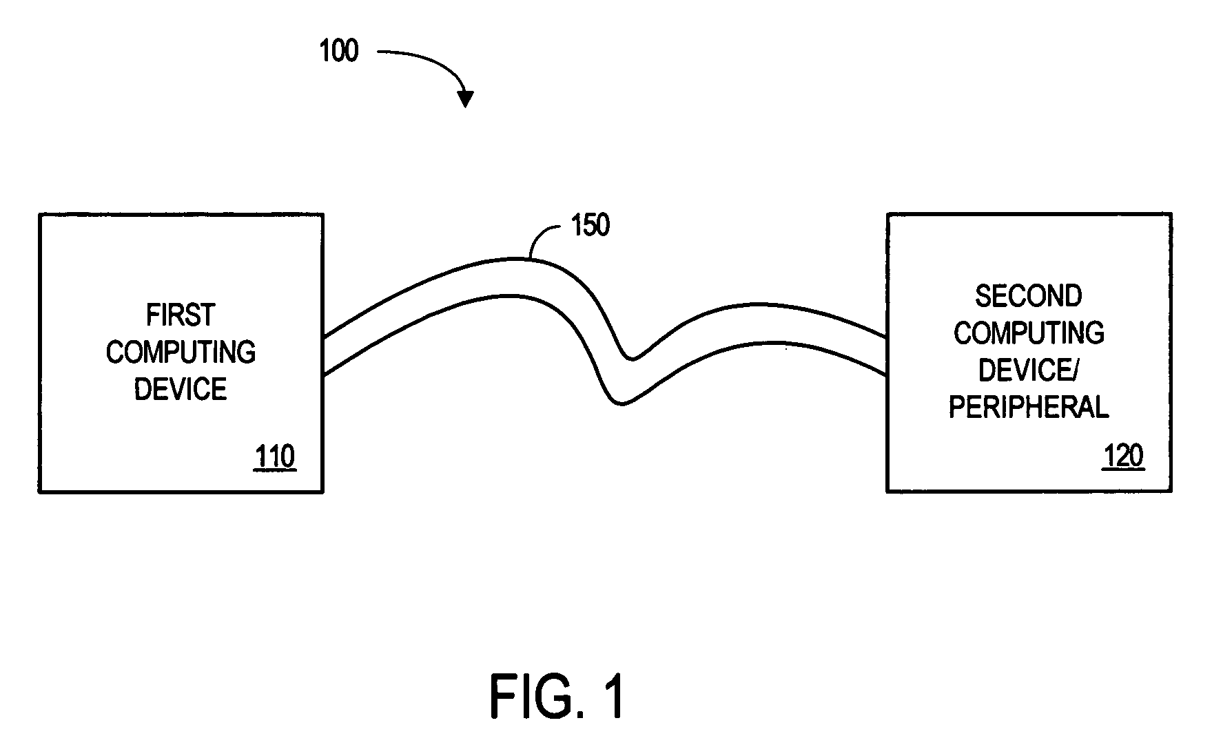
[0011]Computers and other electronic devices may exchange digital information through a cable. For example, FIG. 1 is a block diagram of a system 100 in which a first computing device 110 and a second computing device 120 exchange information via a cable 150. The computing devices 110, 120 might be associated with, for example, a PC, a mobile computer, a server, a computer peripheral (e.g., a printer or display monitor), a storage device (e.g., an external hard disk drive or memory unit), a display device (e.g., a digital television, digital video recorder, or set-top box), or a game device.


PUM


Abstract

According to some embodiments, a waveguide cable includes a dielectric core and a conducting layer surrounding the dielectric core. A first antenna may be provided at a first end of the waveguide cable to receive a digital signal and to propagate an electromagnetic wave through the dielectric core. A second antenna may be provided at a second end of the waveguide cable, opposite the first end, to receive the electromagnetic wave from the dielectric core and to provide the digital signal.

Description

BACKGROUND[0001]Computers and other electronic devices may exchange digital information through a cable. For example, a Personal Computer (PC) might transmit data to another PC or to a peripheral (e.g., a printer) through a coaxial or Category 5 (Cat5) cable. Moreover, the rate at which computers and other electronic devices are able to transmit and / or receive digital information is increasing. As a result, it may be desirable to provide a cable that can transfer information at relatively high data rates, such as 30 Gigahertz (GHz) or higher.BRIEF DESCRIPTION OF THE DRAWINGS[0002]FIG. 1 is a block diagram of a system according to some embodiments.[0003]FIG. 2 is a chart illustrating insertion loss as a function of frequency.[0004]FIG. 3 is cross-sectional view of a waveguide cable according to some embodiments.[0005]FIG. 4 is an antenna for a waveguide cable according to some embodiments.[0006]FIG. 5 is a side cross-sectional view of a waveguide cable according to some embodiments.[...

Claims


Application Information

Patent Timeline
IPC IPC(8): H01P3/14
CPCH01P3/14H01P3/127
Inventor SUAREZ-GARTNER, RICARDOHALL, STEPHENHORINE, BRYCEMOONSHIRAM, ANUSHA
Owner INTEL CORP
Why Eureka
Try Eureka