Photon-counting, non-imaging, direct-detect LADAR

a laser detection and ladar technology, applied in distance measurement, surveying and navigation, instruments, etc., can solve the problems of increasing the cost of the system, and increasing the risk of apd nois

Active Publication Date: 2007-11-27
HARRIS GLOBAL COMMUNICATIONS INC
View PDF20 Cites 116 Cited by
  • Summary
  • Abstract
  • Description
  • Claims
  • Application Information

AI Technical Summary

Benefits of technology

[0012]To meet this and other needs, and in view of its purposes, the present invention provides a light wave rangefinder having a light transmitting optical system for directing a laser pulse at a target, and a light receiving optical system for receiving reflected light from the target, including a Geiger-mode avalanche photodiode (APD) array, and a non-imaging optical device. The non-imaging optical device is positioned between the received reflected light and the APD array, and is configured to uniformly distribute the rece...

Problems solved by technology

This presents a disadvantage for a laser radar system, since cost of the system goes up with use of a higher power transmitter and higher power components.
APDs, however, additionally incorporate a gain mechanism internal to the device itself, making it more sensitive.
This multiplication, however, introduce...

Method used


Image

  • Photon-counting, non-imaging, direct-detect LADAR
  • Photon-counting, non-imaging, direct-detect LADAR
  • Photon-counting, non-imaging, direct-detect LADAR

Examples


Embodiment Construction

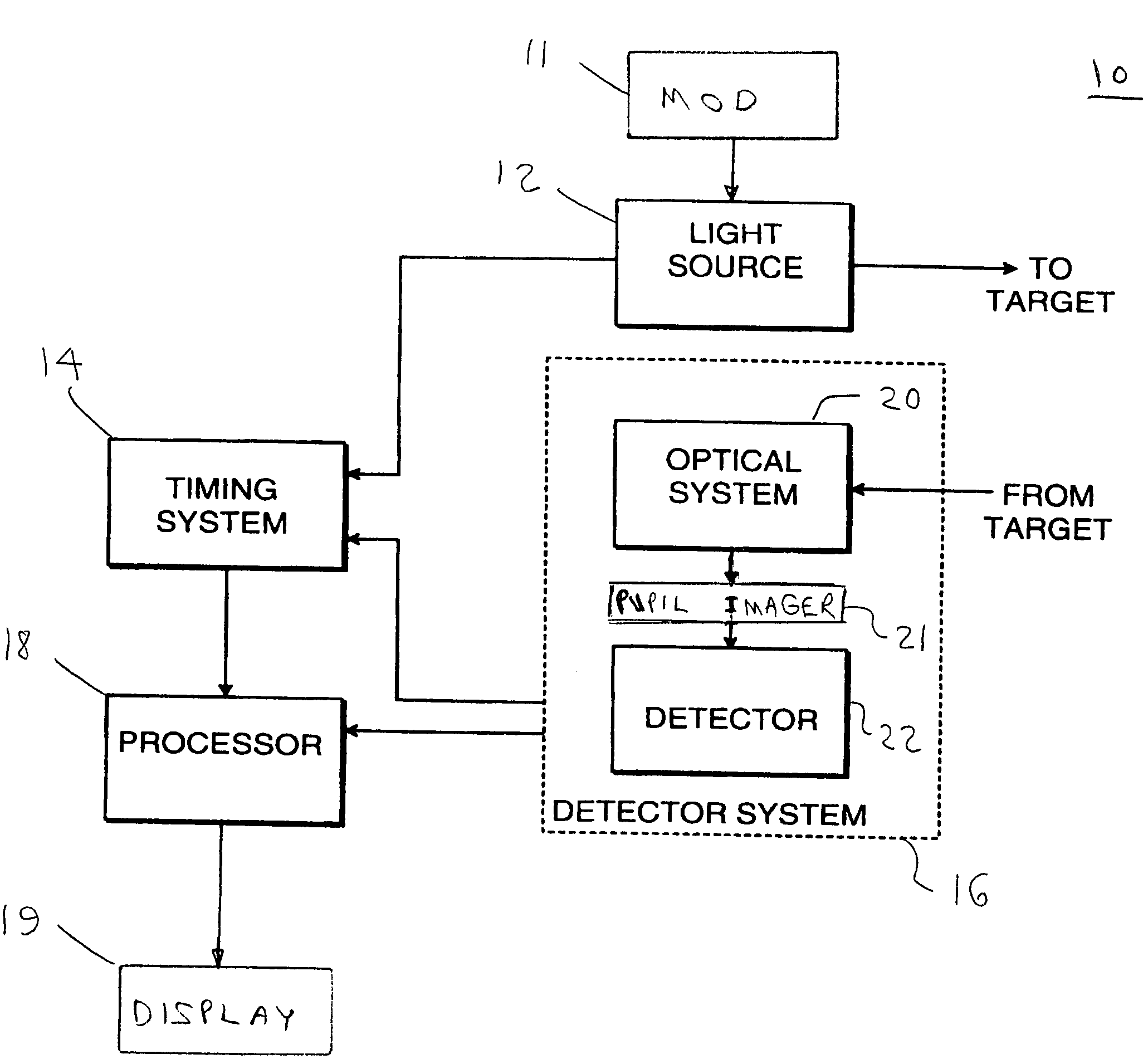
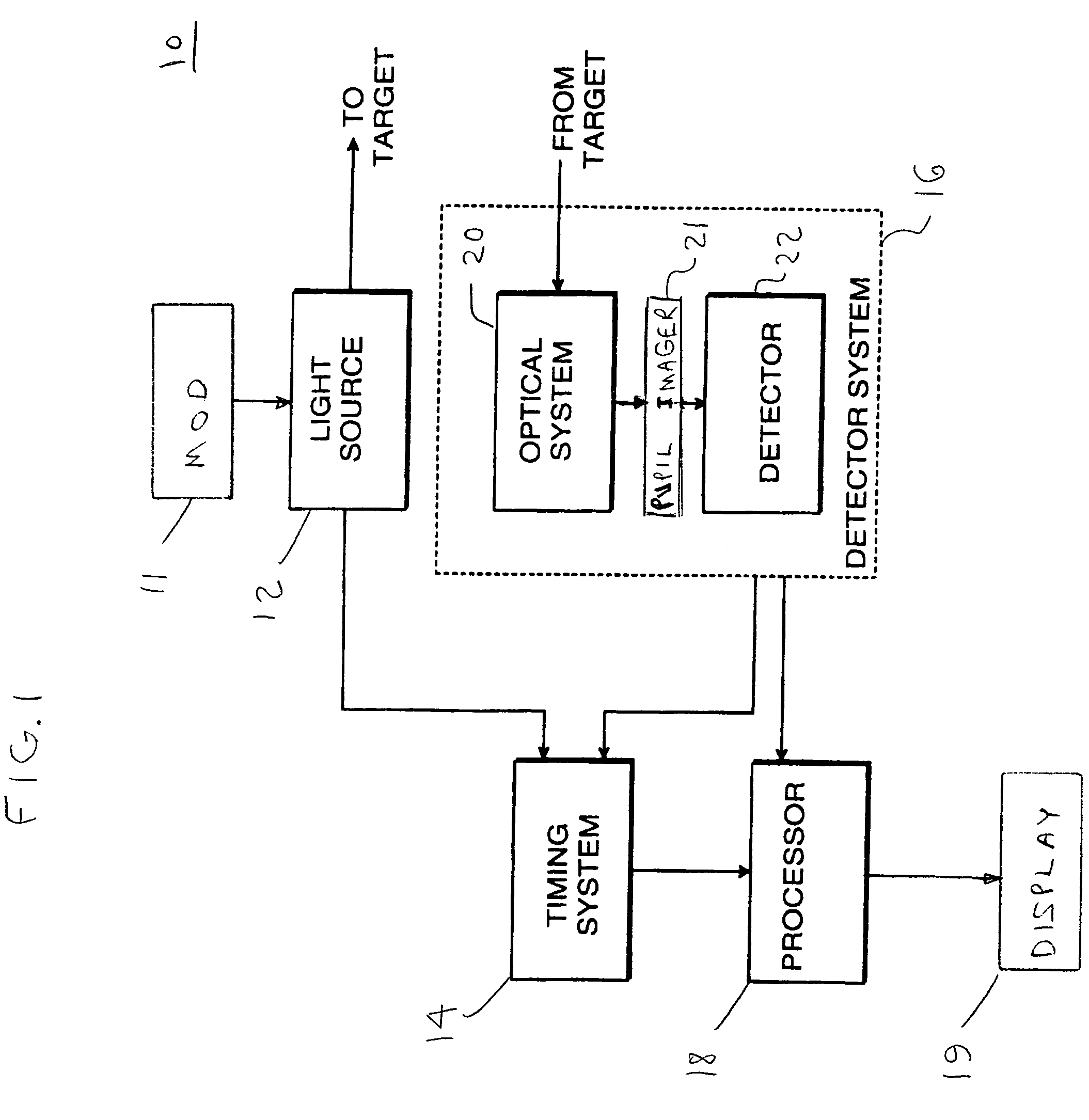
[0025]Referring to FIG. 1, an embodiment of laser rangefinder 10, according to the present invention, includes modulator 11, light source 12, timing system 14, processor 18, display 19, and detector system 16. Rangefinder system 10 may be used to image a single object or a plurality of objects located in a target scene. As shown, light source 12 is modulated by modulator 11 to produce pulses of light which are emitted toward the target being imaged. Light source 12 may include a laser. The laser may be a solid state microchip laser which emits pulses of light having a wavelength, for example, approximately equal to 532 nanometers (nm). When modulated, the laser may emit short pulses of light having a duration, for example, approximately equal to 220 picoseconds.

[0026]The laser may, of course, be any other laser known in the art for use in laser radar systems. The choice of the laser depends on the particular application. For example, in non-visible applications, such as ultra-violet...


PUM


Abstract

A light wave rangefinder includes a light transmitting optical system for directing a laser pulse at a target, and a light receiving optical system for receiving reflected light from the target, including a Geiger-mode avalanche photodiode (APD) array and a non-imaging optical device. The non-imaging optical device is positioned between the received reflected light and the APD array, and is configured to uniformly distribute the received reflected light across the APD array. The APD array is uniformly illuminated by a single received reflected laser pulse, producing a plurality of Geiger-mode avalanche events.

Description

TECHNICAL FIELD[0001]The present invention relates, in general, to a method and apparatus for ranging to a target using a laser detection and ranging (LADAR) system. More specifically, the present invention relates to a LADAR system for determining range to a target, using a Geiger-mode avalanche photodiode (APD) detector array with a non-imaging optical device that evenly distributes reflected light from the target onto the APD detector array.BACKGROUND OF THE INVENTION[0002]Laser radar, also referred to as Light Detection and Ranging (LIDAR) or Laser Detection and Ranging (LADAR), is an active imaging technique which utilizes a laser in a radar system configuration to remotely image a scene and / or range to a target. Laser radar systems utilize principles of optics and microwave radar. Conventional laser radar systems are able to measure the shape, position and velocity of objects in a scene.[0003]Conventional laser radar systems may be broadly divided into two categories: scanning...

Claims


Application Information

Patent Timeline
IPC IPC(8): G01C3/08
CPCG01S17/107G01S17/18
Inventor MENDENHALL, SCOTT N.WHEEL, PETER J.MILLARD, MICHAEL W.
Owner HARRIS GLOBAL COMMUNICATIONS INC
Why Eureka
Try Eureka