Physical quantity sensor having movable portion

a technology of physical quantity sensor and movable portion, which is applied in the direction of shock absorbers, instruments, turn-sensitive devices, etc., can solve the problems of loss of vibration energy, risk, and adverse influence of sensor characteristics, and achieve stable vibration and high accuracy

Inactive Publication Date: 2007-12-04
NIPPON SOKEN +1
View PDF8 Cites 16 Cited by
  • Summary
  • Abstract
  • Description
  • Claims
  • Application Information

AI Technical Summary

Benefits of technology

[0021]In view of the above-described problem, it is an object of the present invention to provide an angular rate sensor. The sensor provides stable vibration for detecting angular velocity with high accuracy.
[0023]In the sensor, the elongated shape of the through holes of each of the driving vibration portion and the detecting vibration portion extends along with the vibrating direction, respectively. Therefore, the air resistance in those directions is reduced when the portion is vibrated. Thus, the damping of each of the driving vibration portion and the detecting vibration portion is reduced so that the vibration of each of the driving vibration portion and the detecting vibration portion can be stabilized. Accordingly, the sensor detects angular velocity with high accuracy.
[0028]In the sensor, since the periphery frame portion has the maximum electric potential, this potential is applied from the periphery frame portion to the support substrate. Accordingly, the potential of the support substrate becomes higher, compared with a conventional sensor. Specifically, the potential of the support substrate is higher than the ground state. Thus, the potential difference between the movable portion and the support substrate becomes smaller so that sticking effect between the movable portion and the support substrate is suppressed.

Problems solved by technology

If the damping happens to occur in both the vibration units, then losses of vibration energy are produced due to this damping.
Accordingly, there is a risk that the vibrations become unstable.
It is apparent that this risk may give an adverse influence to the sensor characteristic.
However, this structure may increase the manufacturing cost of the conventional angular rate sensors, which is not desirable.
As a result, when the mechanical quantity sensor is operated, a large potential difference is produced between the movable unit and the supporting substrate.

Method used


Image

  • Physical quantity sensor having movable portion
  • Physical quantity sensor having movable portion
  • Physical quantity sensor having movable portion

Examples


first embodiment

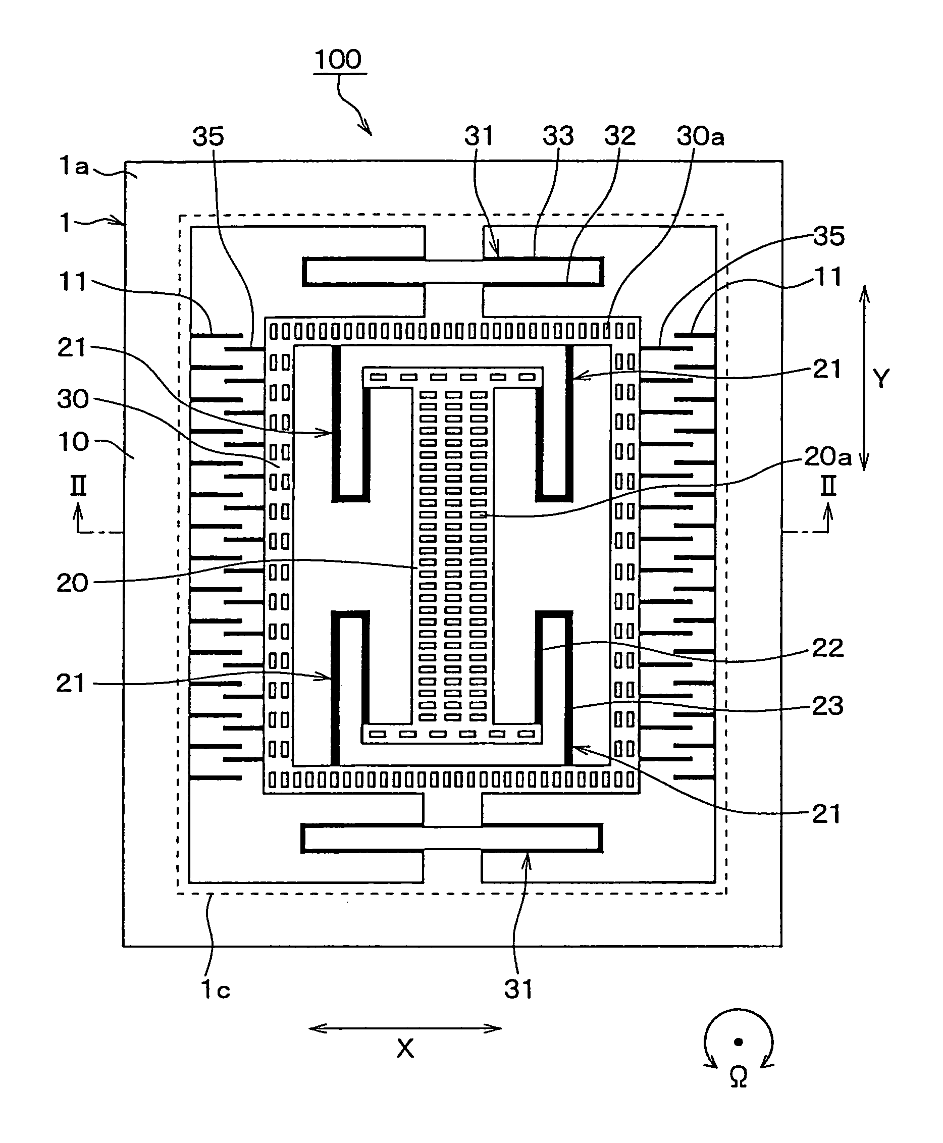
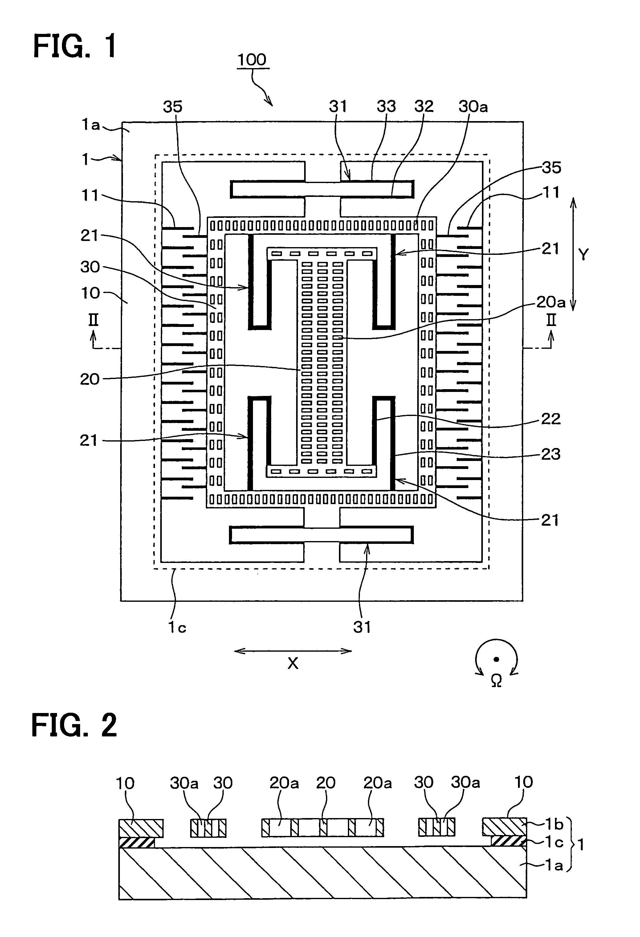
[0037]FIG. 1 is a diagram for schematically representing a plane structure of an angular rate sensor 100 according to a first embodiment mode of the present invention. FIG. 2 is a sectional view for schematically showing the angular rate sensor 100, taken along a dot and dash line II-II shown in FIG. 1.

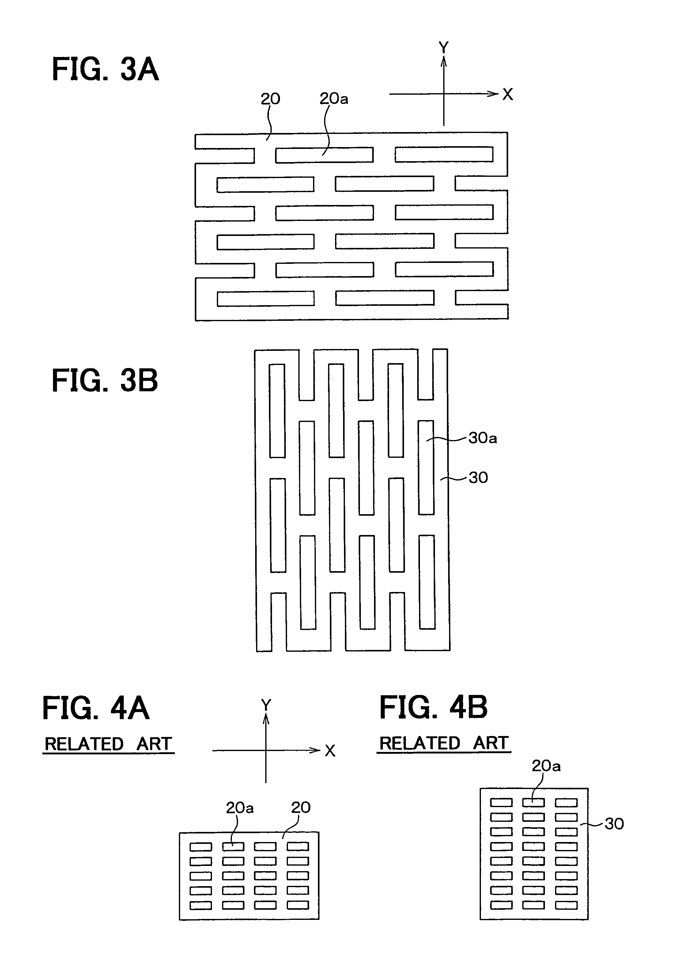
[0038]FIG. 3A is an enlarged plan view for indicating a through hole 20a formed in a drive-purpose vibration unit 20 shown in FIG. 1, and FIG. 3B is an enlarged plan view for showing a through hole 30a formed in a detection-purpose vibration unit 30 shown in FIG. 1.

[0039]This angular rate sensor 100 is manufactured by processing a semiconductor substrate 1 made of a silicon substrate, or the like.

[0040]A structural body is segmented and formed in the semiconductor substrate 1 by forming trenches in this semiconductor substrate 1 by employing a well-known semiconductor manufacturing technique such as an etching process, as shown in FIG. 1, while the structural body includes a frame-sha...

second embodiment

[0080]FIG. 5 is a diagram for schematically representing a plane structure of an angular rate sensor 200 as a mechanical quantity sensor according to a second embodiment mode of the present invention. FIG. 6 is a sectional view for schematically showing the angular rate sensor 200, taken along a dot and dash line VI-VI shown in FIG. 5.

[0081]This angular rate sensor 200 is manufactured by processing the semiconductor substrate 1 made of a silicon substrate, or the like.

[0082]The structural bodies are segmented to be formed in the semiconductor substrate 1 by forming trenches in this semiconductor substrate 1 by employing a well-known semiconductor manufacturing technique such as an etching process, as shown in FIG. 5, while the structural bodies are constituted by the base unit as a frame-shaped peripheral fixing unit 10 functioning as a fixed portion; anchor units 211 and 212; a detecting electrode-purpose fixing unit 213; and further, movable units 20 and 30, etc. The anchor units ...


PUM


Abstract

An angular rate sensor includes: a support substrate; a semiconductor layer; and a movable portion. The movable portion includes a driving vibration portion and a detecting vibration portion. The driving vibration portion is capable of vibrating in a first direction. The detecting vibration portion is capable of vibrating in a second direction. The driving vibration portion includes through holes, and the detecting vibration portion includes thorough holes. Each through hole of the driving vibration portion has an elongated shape extending in the first direction. Each through hole of the detecting vibration portion has an elongated shape extending in the second direction.

Description

CROSS REFERENCE TO RELATED APPLICATIONS[0001]This application is based on Japanese Patent Applications No. 2004-237230 filed on Aug. 17, 2004, and No. 2004-237229 filed on Aug. 17, 2004, the disclosures of which are incorporated herein by references.FIELD OF THE INVENTION[0002]The present invention relates to a physical quantity sensor having a movable portion.BACKGROUND OF THE INVENTION[0003]One type of a physical quantity sensor is an angular rate sensor. As this sort of angular rate sensors, there are angular rate sensors generally manufactured by employing semiconductor substrates. In the general-purpose angular rate sensors, such a sensor is proposed in which a movable unit is constituted by a drive-purpose vibration unit which is vibrated along a first direction, and a detection-purpose vibration unit which is vibrated along a second direction perpendicular to the first direction by Coriolis force. Here, the Coriolis force is generated by applying an angular velocity to the se...

Claims


Application Information

Patent Timeline
Patent Type & Authority Patents(United States)
IPC IPC(8): G01P9/04G01C19/56
CPCG01C19/5719
Inventor ITO, TAKESHIMURATA, MINORU
Owner NIPPON SOKEN
Why Eureka
Try Eureka