Automatic clamp apparatus having lateral motion resistance for IV infusion sets
a clamping apparatus and clamping technology, applied in mechanical devices, engine diaphragms, diaphragm valves, etc., can solve the problems of uncontrollable infusion of medication into the patient, unfavorable “free flow” of medical fluids, and require some manipulation skill on the part of the attending technician, so as to facilitate the insertion of the clamping into the operative position of the infusion pump
- Summary
- Abstract
- Description
- Claims
- Application Information
AI Technical Summary
Benefits of technology
Problems solved by technology
Method used
Image
Examples
Embodiment Construction
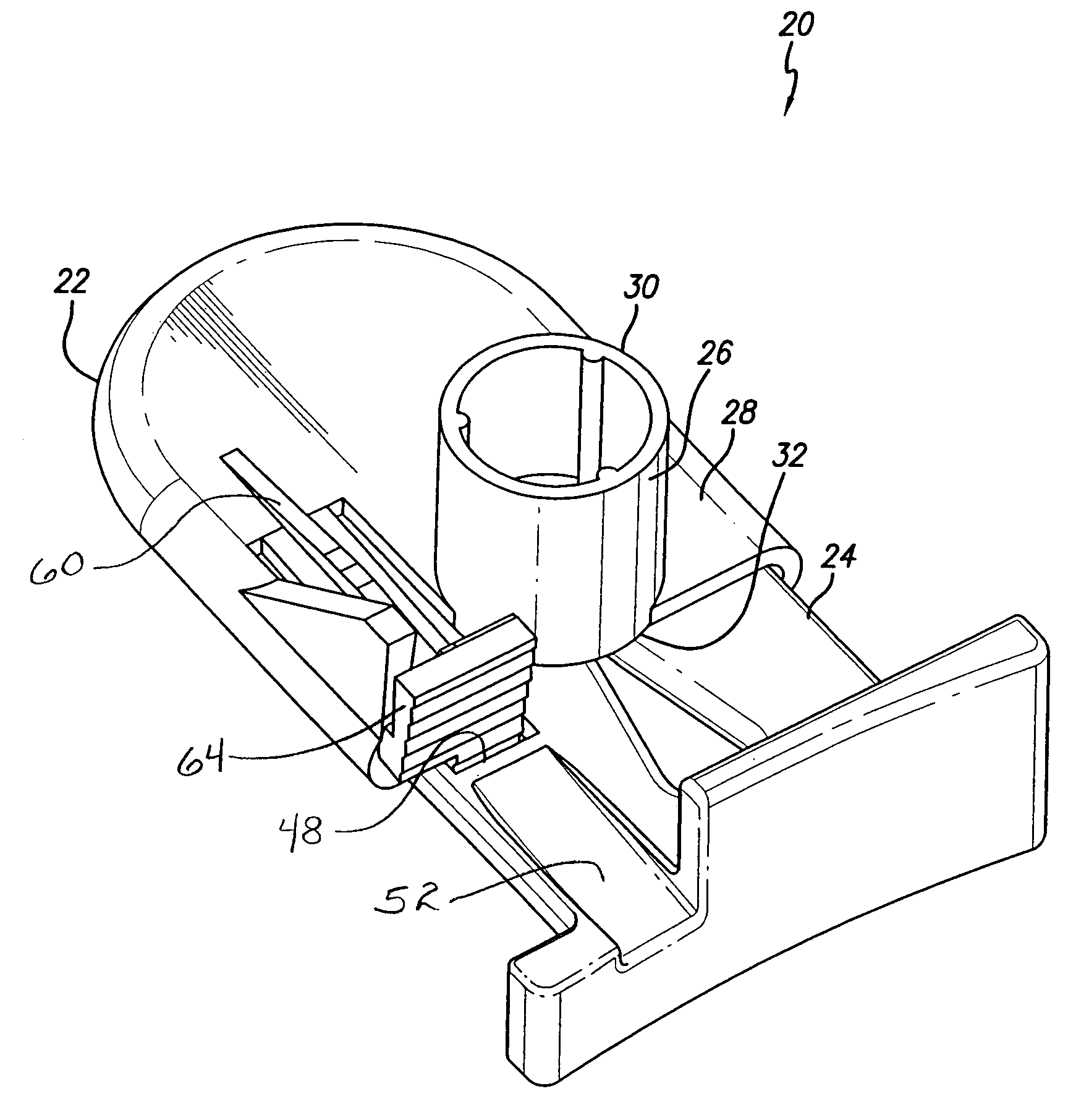
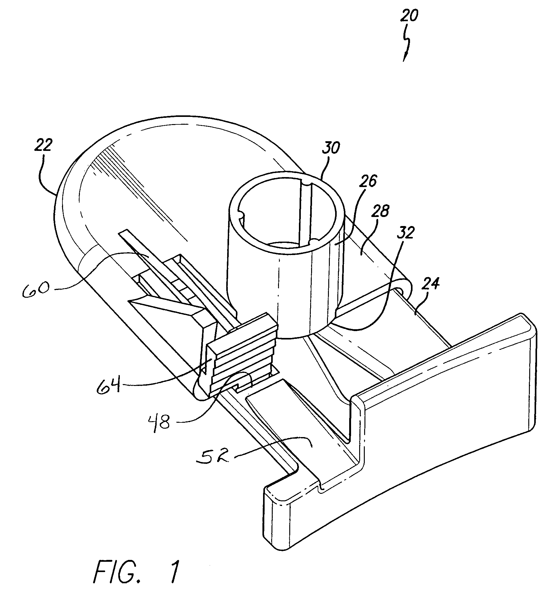
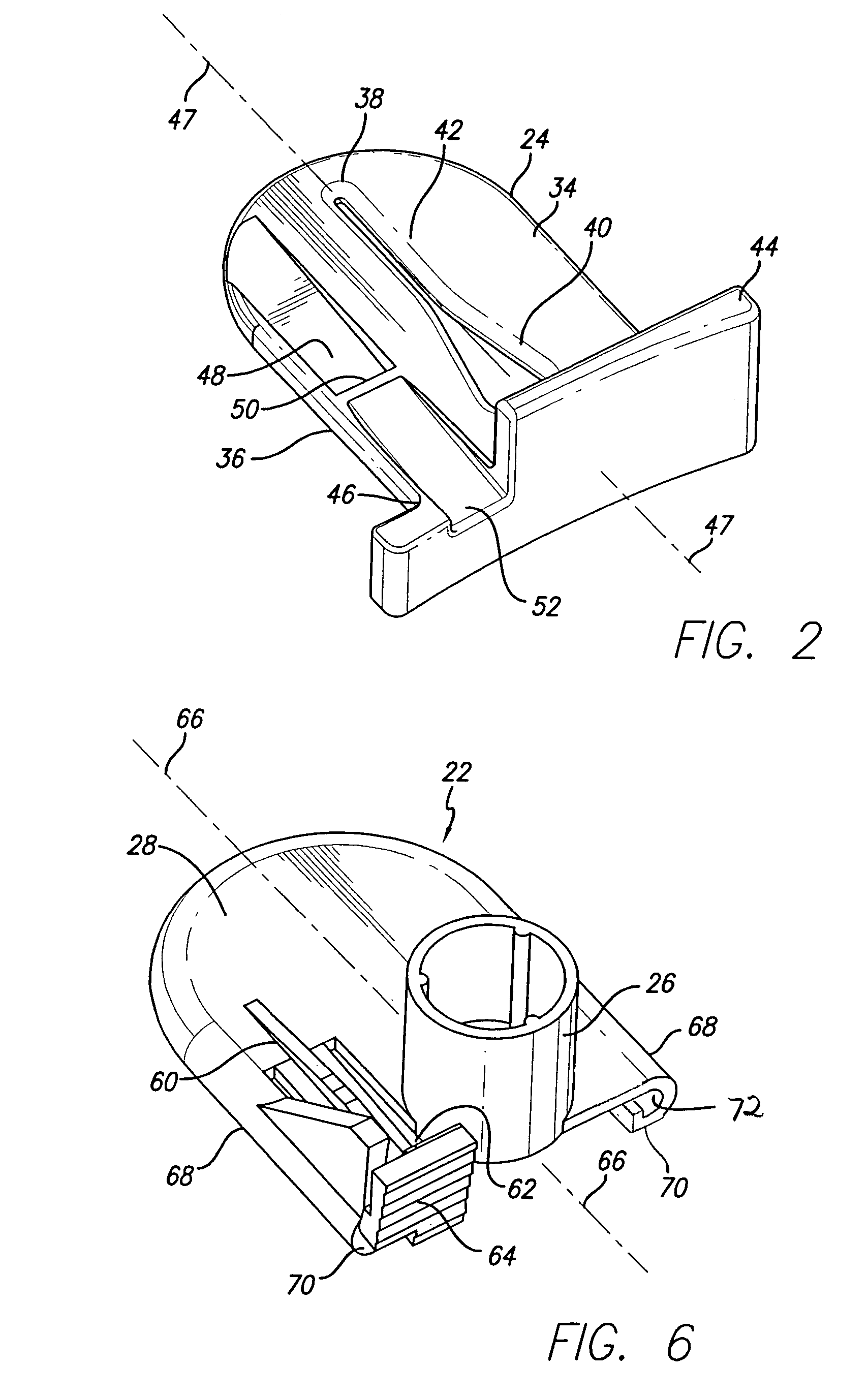
[0038]Referring now to the drawings with more particularity, in which like reference numerals refer to like or corresponding elements among the several views, FIG. 1 presents an automatic clamp apparatus 20 for intravenous (herein referred to as “IV”) infusion sets used in pump devices. The clamp apparatus 20 comprises generally a relatively open, box shaped base or frame 22 and a mating slide clamp 24. Both parts can be formed by injection molding from various plastic materials. The solid body of the slide clamp 24 is shaped and sized to slide within the base 22. In the embodiment shown, the base 22 has a tower 26 formed on the top surface 28 of the base, with the tower extending upwardly from the base and substantially perpendicular to the base. The top end 30 of the tower 26 is formed as a female tube connector into which a resilient IV tube can be attached. A pumping tube or other type of fluid conduit can be attached to the base by other means if desired. The open bottom end 32...
PUM
 Abstract
Description
Claims
Application Information
 - R&D
- Intellectual Property
- Life Sciences
- Materials
- Tech Scout
- Unparalleled Data Quality
- Higher Quality Content
- 60% Fewer Hallucinations
Browse by: Latest US Patents, China's latest patents, Technical Efficacy Thesaurus, Application Domain, Technology Topic, Popular Technical Reports.
© 2025 PatSnap. All rights reserved.Legal|Privacy policy|Modern Slavery Act Transparency Statement|Sitemap|About US| Contact US: help@patsnap.com


