
Buckling actuator

a technology of actuators and actuators, applied in the direction of generators/motors, relays, instruments, etc., can solve the problems of large voltage applied to comb-like electrodes, difficulty in providing a design that allows the barrier e′ of potential energy, and conventional art problems, and achieves the effect of high energy barrier

Inactive Publication Date: 2007-12-04
MURATA MFG CO LTD
View PDF7 Cites 22 Cited by
  • Summary
  • Abstract
  • Description
  • Claims
  • Application Information

AI Technical Summary

Benefits of technology

[0017]In order to overcome the problems described above, preferred embodiments of the present invention provide a highly-reliable buckling actuator in which a movable member can be stably shifted in a predetermined direction and a high energy barrier is set between switch positions so as to prevent, for example, short circuits and improper operations.

Problems solved by technology

However, according to the conventional art, it is difficult to provide a design that allows the barrier ΔE′ of potential energy to be large since the supporting beams are in a completely restrained state.
For this reason, the conventional art is problematic in view of the fact that the voltage applied to the comb-like electrodes must be large.
Although the electrostatic force is originally applied to the comb-like electrodes only in the longitudinal direction, if the voltage applied is large, the force components of the electrostatic force in a direction perpendicular to the longitudinal direction may undesirably be applied to the movable member due to an imbalanced electrostatic force caused by, for example, inconsistent processing.
This may cause the comb-like electrode of the movable member to come into contact with the comb-like electrode of the substrate, and may thus lead to a short circuit between the electrodes.
Accordingly, this may result in a malfunction of the actuator.
However, since the supporting beams can be moved easily in the width direction of the movable member, this structure may be problematic in that the supporting beams may cause the comb-like electrodes to come into contact with each other, thereby causing a short and malfunction of the device as described above.
This is problematic in that the movable member may automatically be shifted even with, for example, a small external impact, thus leading to improper operation and low reliability of the optical switch device.

Method used


Image

  • Buckling actuator
  • Buckling actuator
  • Buckling actuator

Examples


Embodiment Construction

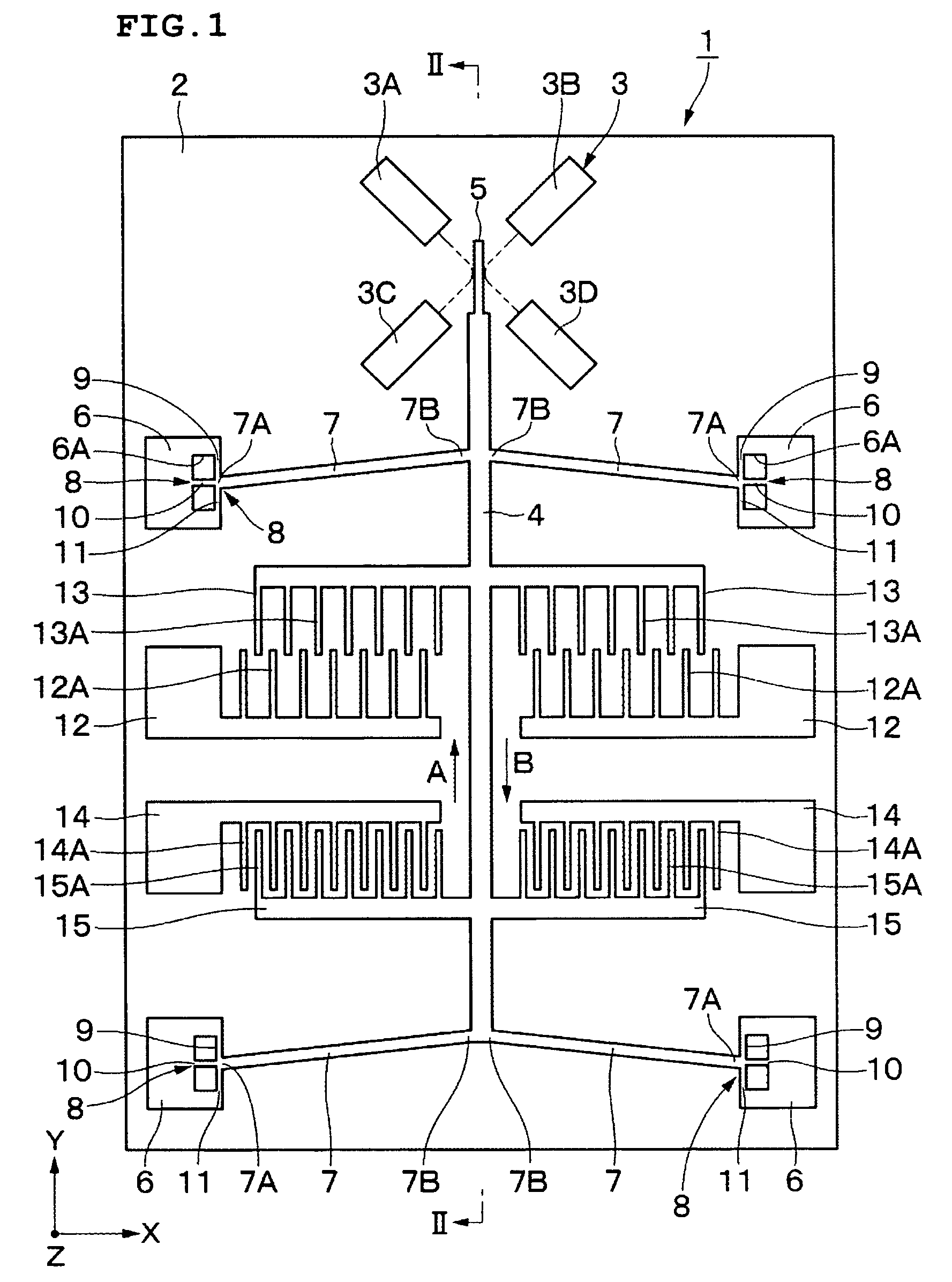
[0057]Preferred embodiments of a buckling actuator according to the present invention will now be described with reference to the drawings.

[0058]FIGS. 1 to 8 illustrate a first preferred embodiment in which a buckling actuator is preferably used, for example, as an optical switch device.

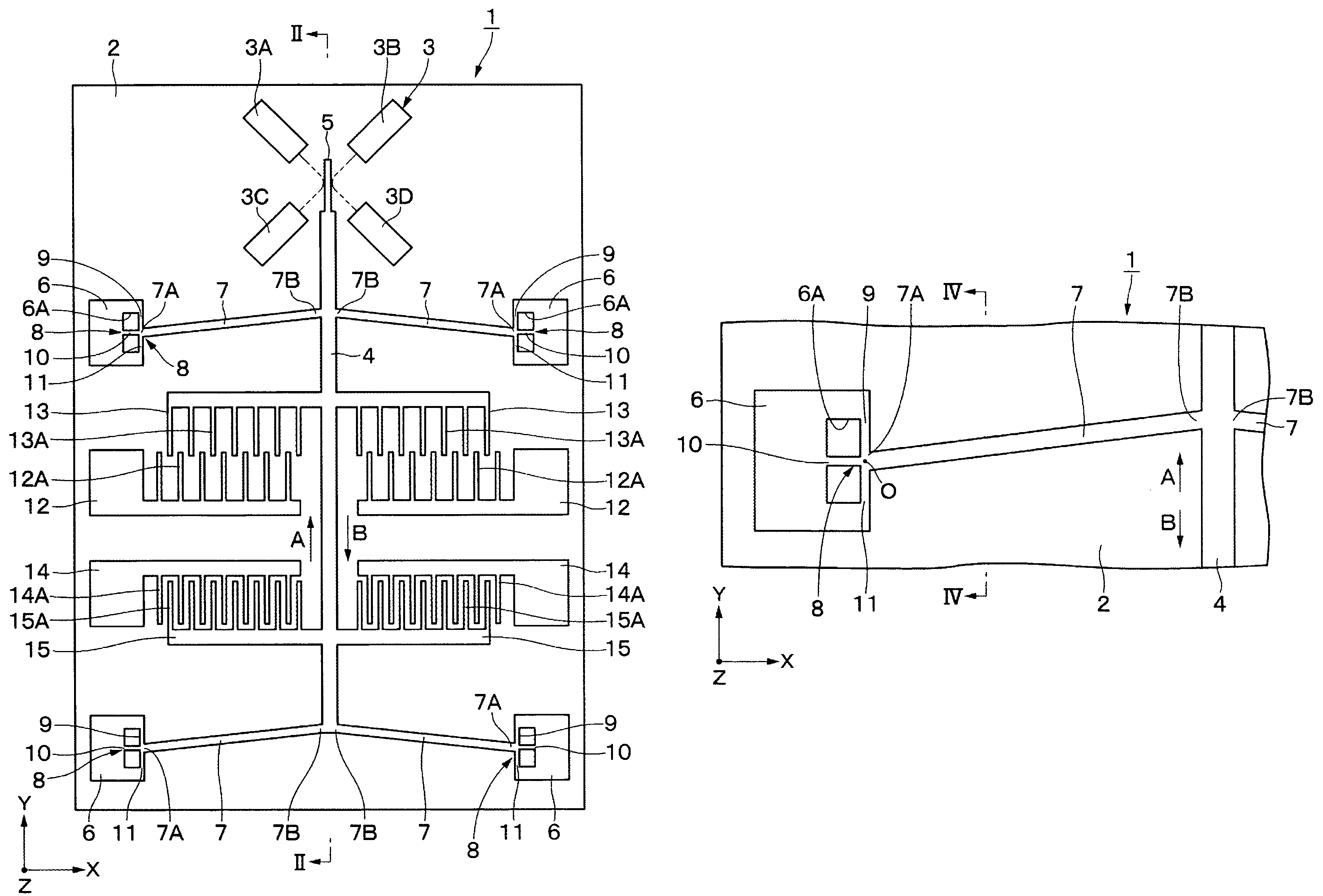
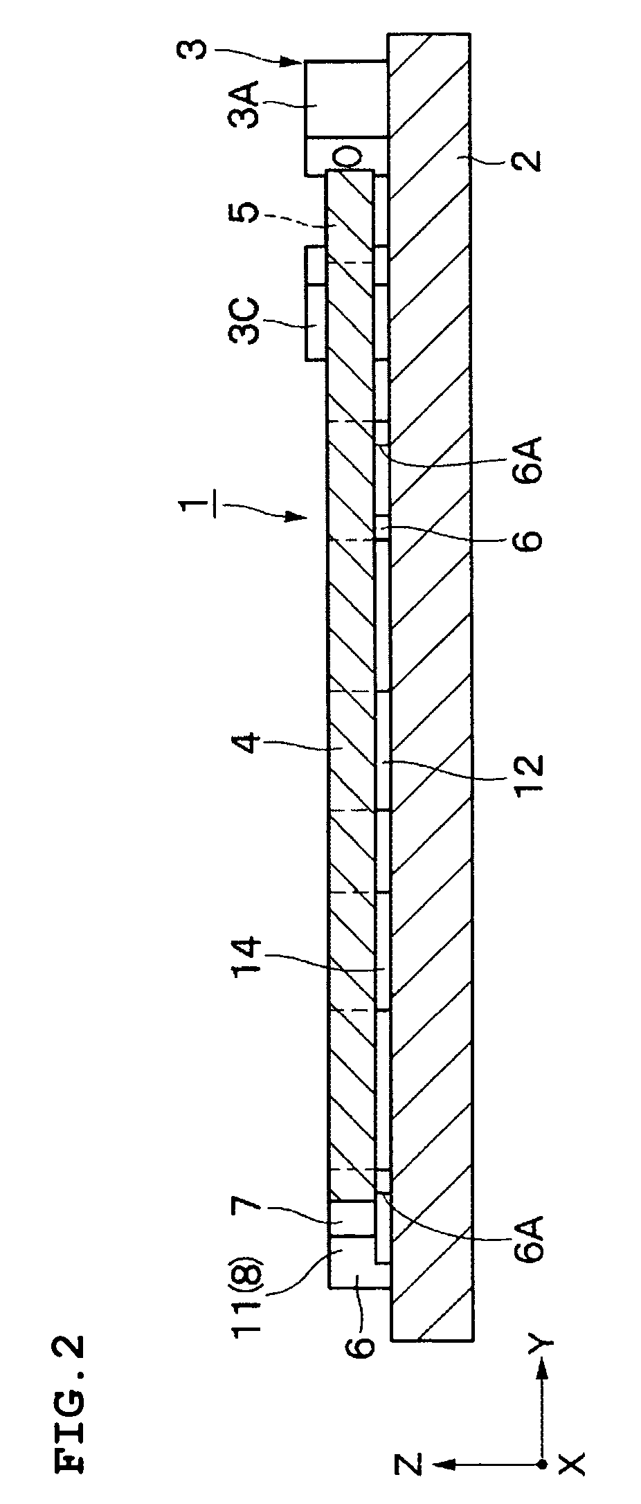
[0059]In the drawings, reference numeral 1 indicates an optical switch device, and reference numeral 2 indicates a substrate which functions as a base for the optical switch device 1. The substrate 2 is preferably formed of, for example, a substantially rectangular glass plate which is several millimeters in size. The substrate 2 has an x-axis, a y-axis, and a z-axis which are substantially perpendicular to one another. The substrate 2, for example, extends horizontally along the x-axis and the y-axis.

[0060]Furthermore, the front surface of the substrate 2 is preferably provided with, for example, a low-resistance single-crystal silicon material, which is etched to form a movable member 4; a mirror 5...


PUM


Abstract

A buckling actuator has a connecting section of a supporting beam that is provided with a rotatable supporter for allowing a movable member to be stably maintained at one of two switch positions. A substrate, stationary members, rotatable supporters, and supporting beams support a movable member in a shiftable manner in a y-axis direction, such that the movable member can be shifted between first and second switch positions. Moreover, the rotatable supporters are each provided with arm portions which extend in a radial fashion and support the corresponding supporting beam in a rotatable manner. When the movable member is being shifted, each supporting beam can be rotated without having to bend a corresponding end by a significant amount. Thus, a large barrier ΔE of potential energy of the movable member is set between the first and second switch positions. The movable member can therefore be stably maintained at each of the switch positions even when electric power is not supplied to electrodes. Furthermore, each arm portion prevents the movable member from being displaced in an x-axis direction.

Description

BACKGROUND OF THE INVENTION[0001]1. Field of the Invention[0002]The present invention relates to buckling actuators used as, for example, optical switch devices and optical shutters, in which supporting beams can be buckled in order to shift a movable member between two alternative positions.[0003]2. Description of the Related Art[0004]Generally, buckling actuators are used as optical switch devices which perform switching of an optical path by shifting a movable member (for example, see U.S. Pat. No. 6,360,033 which is hereinafter referred to as Patent Document 1; and U.S. Pat. No. 6,303,885 which is hereinafter referred to as Patent Document 2).[0005]Conventional optical switch devices generally include a substrate, a movable member disposed above the substrate and being shiftable in a predetermined shifting direction, a stationary member which is disposed on the substrate and supports the movable member, a plurality of supporting beams each of which is connected between the stati...

Claims


Application Information

Patent Timeline
Patent Type & Authority Patents(United States)
IPC IPC(8): H01H51/22G02B6/35H02N1/00
CPCB81B3/0051H02N1/008G02B6/358G02B26/0833B81B2201/033B81B2201/045G02B6/3514G02B6/3518G02B6/357G02B6/3572G02B6/3584G02B6/3544B81B3/0083B81B2203/0163
Inventor TAMURA, MASAYAKOBAYASHI, SHINJI
Owner MURATA MFG CO LTD
Learn More