
Toroidal inductor design for improved Q

a technology of inductor and quality factor, applied in the field of inductors, can solve problems such as the reduction of the quality factor (q) of the inductor

Active Publication Date: 2007-12-04
HARRIS CORP
View PDF10 Cites 25 Cited by
  • Summary
  • Abstract
  • Description
  • Claims
  • Application Information

AI Technical Summary

Problems solved by technology

Notably, an increase in the value of DCR will cause a decrease in the quality factor (Q) of the inductor.

Method used


Image

  • Toroidal inductor design for improved Q
  • Toroidal inductor design for improved Q
  • Toroidal inductor design for improved Q

Examples


Embodiment Construction

[0034]The invention concerns an improved toroidal inductor integrated within a ceramic substrate and a method of making same. For convenience, the substrate is described herein as a ceramic substrate. However, it should be understood that the invention is not limited in this regard. Substrates formed of other material can also be used. For example, such materials include, but are not limited to liquid crystal polymer (LCP), polymer film, polyimide film, epoxy laminates, or semiconductor materials such as silicon, gallium arsenide, gallium nitride, germanium or indium phosphide.

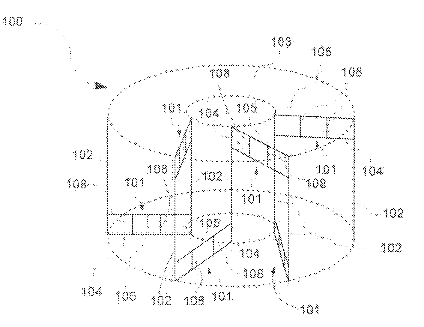
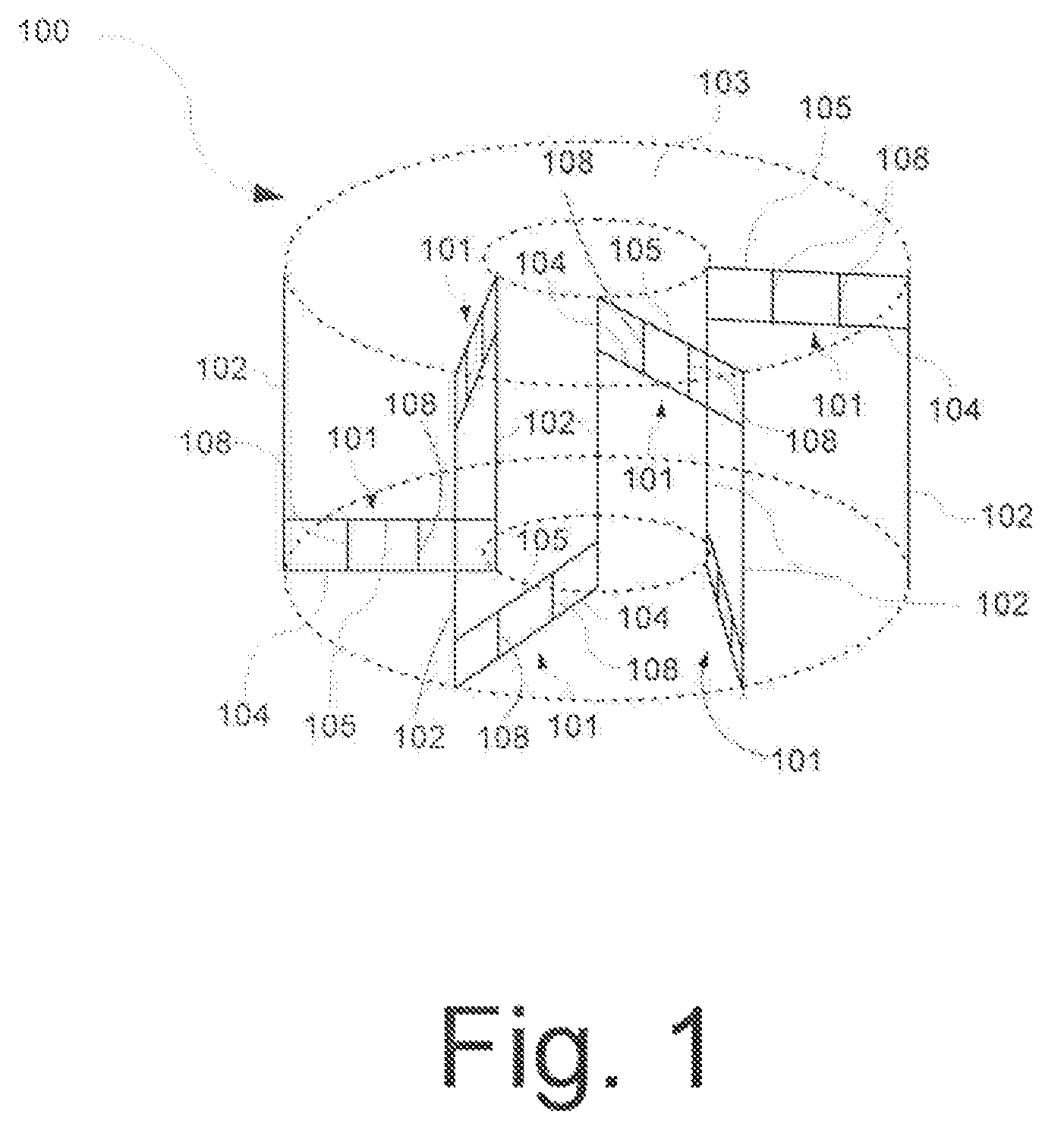
[0035]Referring to FIG. 1, a schematic representation of the improved toroidal inductor 100 is shown. The inductor 100 comprises a coil formed of an elongated conductor defining a plurality of turns and extending around a core material 103. The improved toroidal coil structure includes a plurality of coil segments arranged in an alternating pattern. The coil segments include a first type coil segment 101 and a...


PUM

PropertyMeasurementUnit
temperatureaaaaaaaaaa
lengthsaaaaaaaaaa
conductiveaaaaaaaaaa

Abstract

A toroidal inductor (100) and method of forming same. The invention is intended to decrease the direct current resistance (DCR) of the toroidal inductor circuit. Thus, an increase in the quality factor (Q) of the circuit is produced. The toroidal inductor includes a coil formed from an elongated conductor extending around a core material and defining a plurality of turns. The elongated conductor is comprised of one or more coil segments. The coil segments are arranged in an alternating pattern of a first type segment (101) and a second type segment (102). Each of the coil segments of the first type includes a plurality of elongated parallel conductors (104, 105) spaced apart and electrically connected by conductive links (108) at predetermined intervals along their respective lengths. The coil segments of the second type are formed of a single conductor defined by a conductive via (302, 304) formed in the substrate.

Description

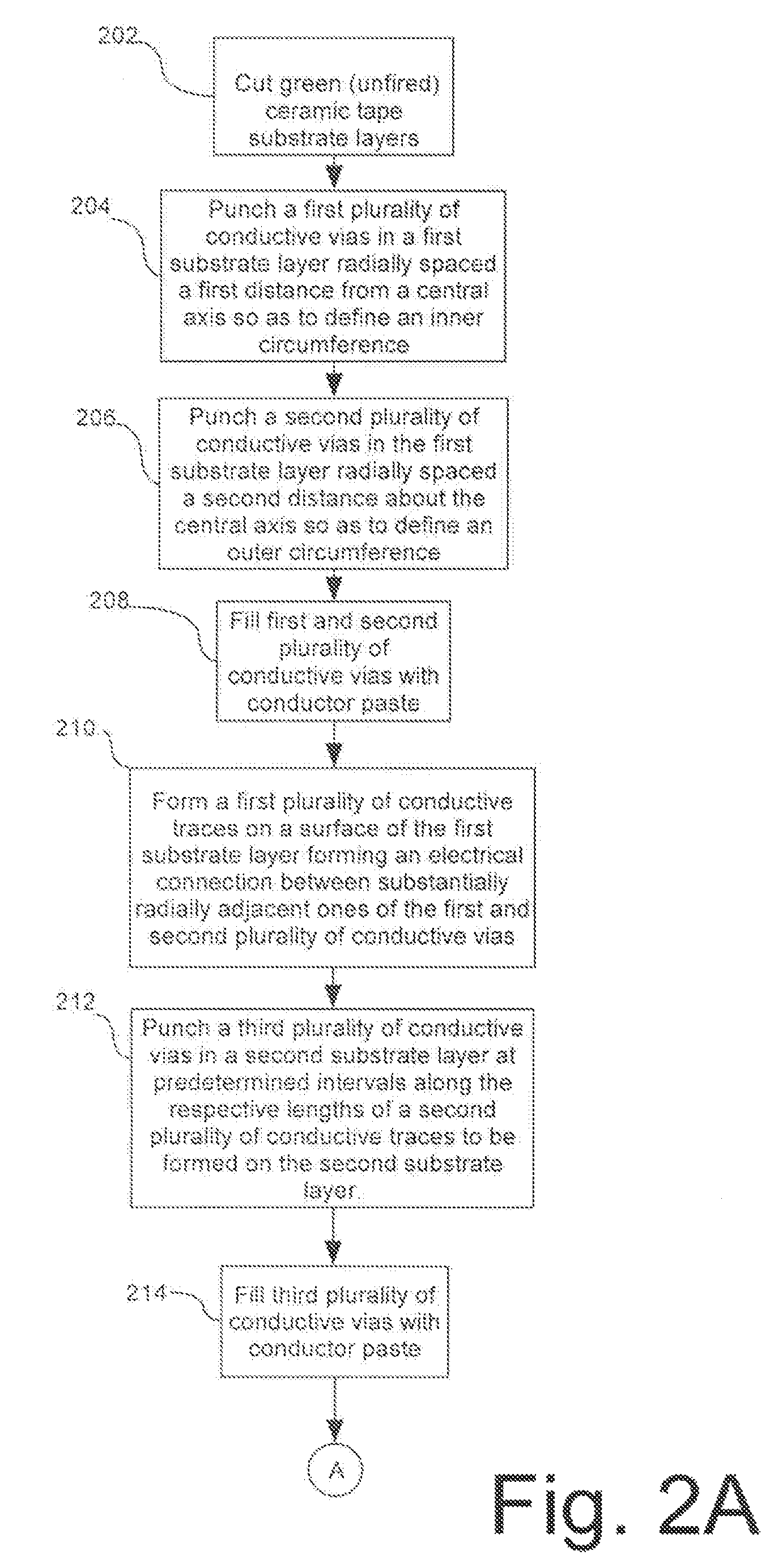
BACKGROUND[0001]1. Statement of the Technical Field[0002]The inventive arrangements relate generally to inductors and more particularly to toroidal inductors.[0003]2. Description of the Related Art[0004]Embedded toroidal inductors are known in the art. For example, U.S. Pat. No. 6,990,729 to Pleskach et al. discloses a method for forming an embedded toroidal inductor. The method includes the step of forming in a ceramic substrate a first plurality of conductive vias radially spaced a first distance from a central axis so as to define an inner circumference. A second plurality of conductive vias is formed radially spaced a second distance about the central axis so as to define an outer circumference. A first plurality of conductive traces forming an electrical connection between substantially adjacent ones of the first and second plurality of conductive vias is formed on a first surface of the ceramic substrate. Further, a second plurality of conductive traces forming an electrical c...

Claims


Application Information

Patent Timeline
Patent Type & Authority Patents(United States)
IPC IPC(8): H01F5/00
CPCH01F17/0033H01F17/0013Y10T29/49073H01F2027/2814Y10T29/4902H01F17/062
Inventor PLESKACH, MICHAEL D.PAYAN, BAYARDO A.PROVO, TERRY
Owner HARRIS CORP
Learn More