Hydraulic unit

a technology applied in the direction of servomotors, servomotor components, fluid-pressure actuators, etc., can solve the problems of increasing the lifespan of hydraulic units and grippers, and achieve the effect of stroke speed

Inactive Publication Date: 2007-12-11
SCHULER AUTOMATION
View PDF3 Cites 0 Cited by
  • Summary
  • Abstract
  • Description
  • Claims
  • Application Information

AI Technical Summary

Benefits of technology

[0016]According to a further embodiment, the delay unit has a bypass with a one-way valve connected therein. This makes it possible to push back the piston quickly to its end position. Using a gripper equipped with the hydraulic unit provided by the invention, the stroke speed with which the work pieces are gripped can be increased.
[0017]It is useful that a spring be provided in the auxiliary cylinder with which spring the auxiliary piston is forced to the starting position. The piston has no stroke in the starting position. The provision of a spring makes it simple to return the piston to the starting position and is not prone to malfunction.
[0018]According to a further embodiment, it is provided that the delay unit be connected in a first or second line connected with the hydraulic cylinder. The suggested construction is simple. In particular, it is not necessary to connect the delay unit in a separate bypass on the hydraulic cylinder.

Problems solved by technology

This increases the lifespan of the hydraulic unit and the grippers.

Method used


Image

  • Hydraulic unit
  • Hydraulic unit
  • Hydraulic unit

Examples


Embodiment Construction

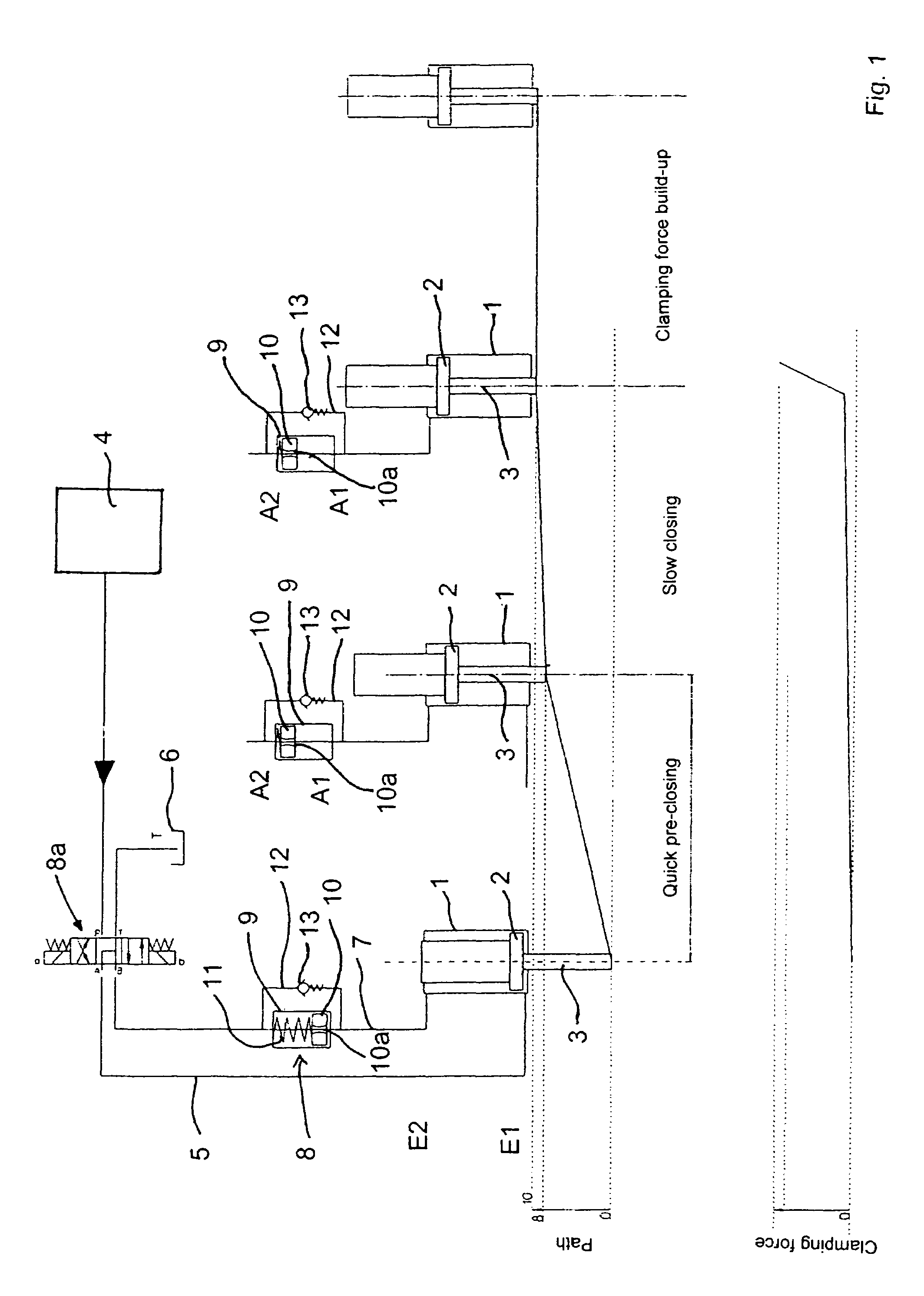
[0026]In FIG. 1, a hydraulic cylinder 1 contains a piston 2 with a piston rod 3. A source of pressure 4 is hydraulically connected via a first line 5 with the one end E1 of the hydraulic cylinder 1. The other end E2 of the hydraulic cylinder 1 has a second line 7 connected with a fluid reservoir 6. The pressure source 4 can form a construction unit together with the fluid reservoir 6. It is useful that the liquid used here is oil, in particular hydraulic oil. A delay unit 8 is connected in the second line 7. The pressure source 4 and the liquid reservoir 6 can be circuited via a switch-over unit 8a to either the first 5 or the second line 7. This means that either the first 5 or the second line 7 can be provided with pressure and the other line 5 or 7 does not have pressure.

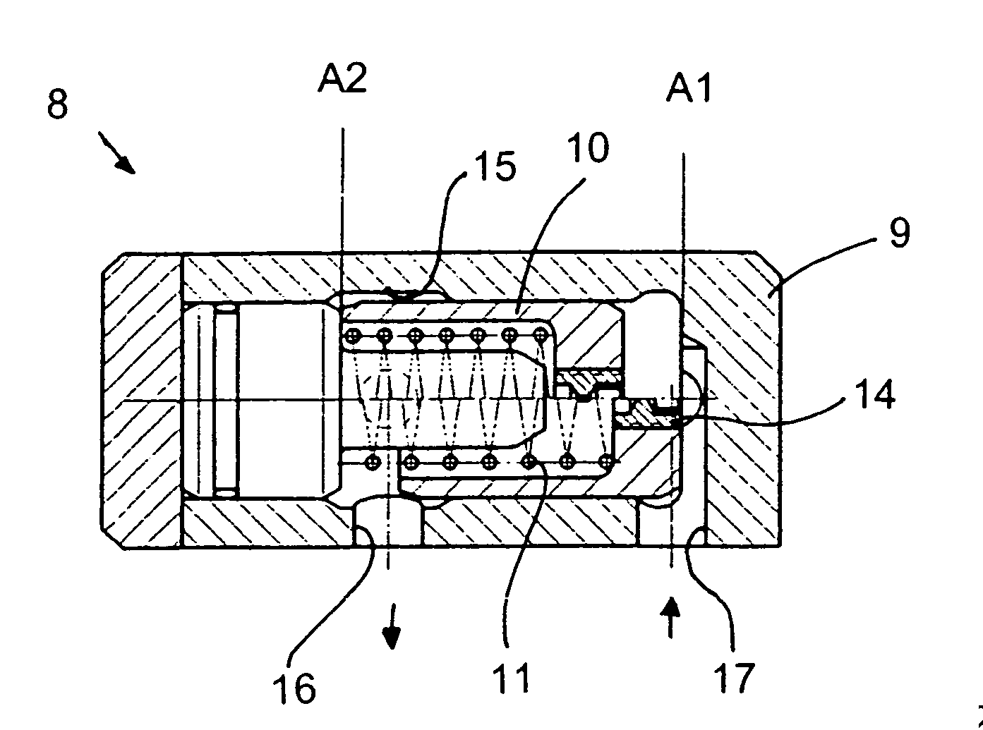
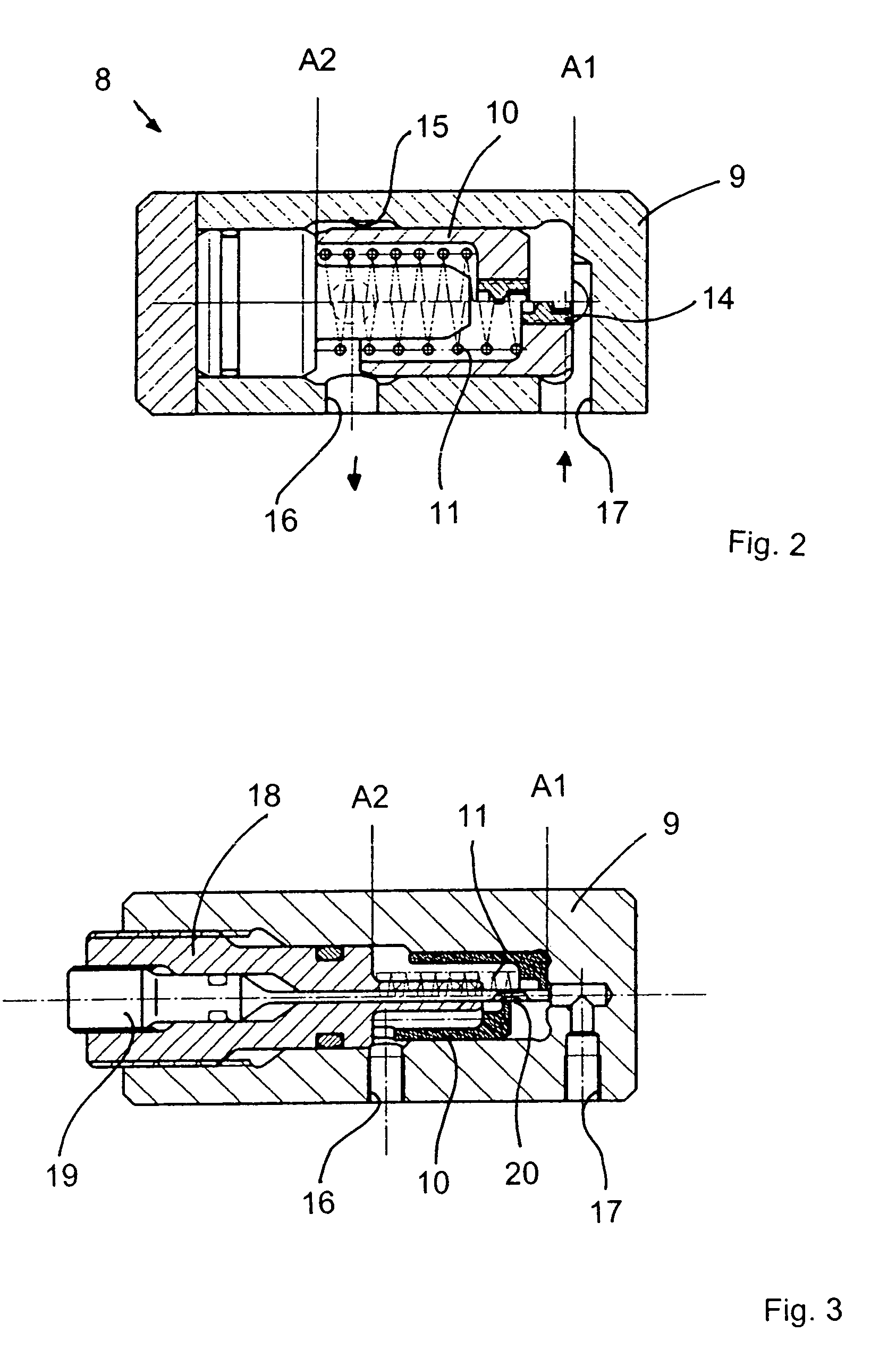
[0027]The delay unit 8 is equipped with an auxiliary cylinder 9 and an auxiliary piston 10 contained therein. The auxiliary piston 10 is provided with a throttle valve 10a. A spring 11 forces the auxiliary piston...


PUM


Abstract

An hydraulic unit includes a hydraulic cylinder, and a piston retained in the hydraulic cylinder, wherein the piston can be moved from a first end position located at one end of the hydraulic cylinder to a second end position located at the opposite other end position of the hydraulic cylinder. The hydraulic cylinder is hydraulically connected with a delay unit which is equipped with an auxiliary cylinder containing an auxiliary piston, with which a movement of the piston can be delayed in a middle section located between the first and the second end position. The auxiliary cylinder has a first and a second opening for incoming and outgoing hydraulic oil. In order to precisely set an attenuation point, a throttle valve provided on the auxiliary cylinder or piston be connected in the flow path.

Description

RELATED APPLICATIONS[0001]The present application is based on, and claims priority from, German Application Number 10 2004 039 483.0, filed Aug. 14, 2004, the disclosure of which is hereby incorporated by reference herein in its entirety.BACKGROUND OF THE INVENTION[0002]The invention relates to a hydraulic unit.[0003]Such a hydraulic unit is known from DD 46 600.[0004]The known hydraulic unit has the disadvantage that a delayed movement of a piston in a section of the hydraulic cylinder located between the first and second end position is not possible for a precisely specified position.[0005]Such hydraulic units are widely known in accordance with the state of technology. For example, they are used to generate an opening and closing movement of a gripper installed on a transfer. To attenuate the opening and closing movement of the gripper at the end of the particular path of motion, one usually uses hydraulic cylinders with a so-called end position attenuation. With this, the hydrau...

Claims


Application Information

Patent Timeline
Patent Type & Authority Patents(United States)
IPC IPC(8): F15B15/22F15B11/13
CPCF15B15/228
Inventor SCHRADI, PETER
Owner SCHULER AUTOMATION
Why Eureka
Try Eureka