Image forming apparatus and image processing method

a technology of image forming apparatus and image processing method, which is applied in the direction of digitally marking record carriers, visual presentation using printers, instruments, etc., can solve the problems of non-uniform density, limitation of density non-uniformity correction, and inability to achieve uniform density correction, so as to prevent the degradation of granularity of images and reduce density non-uniformities

Inactive Publication Date: 2007-12-11
FUJIFILM CORP
View PDF5 Cites 13 Cited by
  • Summary
  • Abstract
  • Description
  • Claims
  • Application Information

AI Technical Summary

Benefits of technology

[0010]The present invention has been contrived in view of the foregoing circumstances, an object thereof being to provide an image forming apparatus and image processing method whereby density non-uniformities in an image formed on a recording medium can be reduced, while also preventing deterioration of the granularity of the image.
[0011]In order to attain the aforementioned object, the present invention is directed to an image forming apparatus which forms an image on a prescribed recording medium by carrying out digital halftoning using a threshold value matrix, the apparatus comprising: a plurality of nozzles which eject ink toward the recording medium to form an image; an ejection characteristics determination device which determines ejection characteristics of each of the nozzles; and a threshold value correction device which performs first threshold value correction to reduce density non-uniformity occurring in the image due to error in the ejection characteristics of the nozzles, by correcting the threshold value matrix according to the error in the ejection characteristics of the nozzles, and performs second threshold value correction to reduce granularity in the image by correcting the threshold value matrix having undergone the first threshold value correction, according to threshold values in the threshold value matrix.
[0012]According to the present invention, density non-uniformity in the image is reduced by correcting the threshold value matrix on the basis of the error in the ejection characteristics of the nozzles, while at the same time, the granularity of the image is reduced by further correcting the threshold value matrix thus corrected, on the basis of the threshold values in the threshold value matrix. Consequently, it is not necessary to provide correction limits, and furthermore, by optimizing the threshold value matrix in advance, prior to on-demand image formation, it is -possible to form images of high-quality on demand at high-speed, while achieving satisfactory correction of density non-uniformities and avoiding deterioration of the granularity of the image.

Problems solved by technology

In an image forming apparatus of this kind, if there is a nozzle having a larger droplet ejection volume (or a smaller droplet ejection volume) than the other nozzles, then non-uniformity in density which is visible as banding occurs in the image formed on the recording medium.
However, if the image data is corrected in order to reduce non-uniformities in density, then generally, the granularity of the image formed on the recording medium becomes worse.
However, if the upper and lower limit values are provided for correction of the image data, then this places limitations on the correction of density non-uniformities, and therefore density non-uniformities may not be corrected sufficiently in cases where the droplet ejection error of a nozzle exceeds the limit of the correction.
However, if the normal density dots are switched to the low-density dots using droplet ejection of light-colored ink, then since this method is premised on the use of light-colored inks, it cannot be applied to image forming apparatuses which do not use light-colored inks.
Moreover, in a method using light-colored inks of this kind, it is not possible to perform correction to increase the density of the dots.

Method used


Image

  • Image forming apparatus and image processing method
  • Image forming apparatus and image processing method
  • Image forming apparatus and image processing method

Examples


Embodiment Construction

General Composition of Image Forming Apparatus

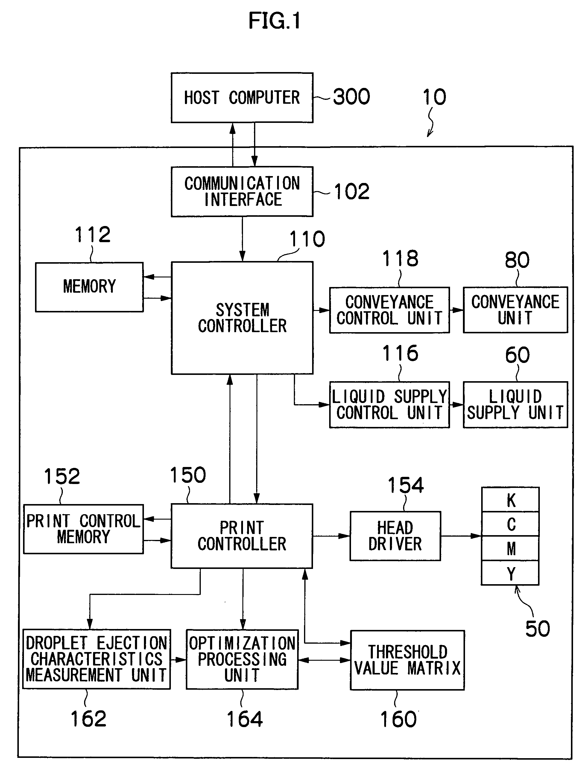
[0057]FIG. 1 is a block diagram showing the general composition of an image forming apparatus according to an embodiment of the present invention.

[0058]In FIG. 1, the image forming apparatus 10 according to the present embodiment comprises an inkjet head 50, a liquid supply unit 60, a conveyance unit 80, a communication interface 102, a system controller 110, a memory 112 (memory for system controller), a liquid supply control unit 116, a conveyance control unit 118, a print controller 150, a print control memory 152, a head driver 154, a threshold value matrix 160, a droplet ejection characteristics measurement unit 162 (ejection characteristics determination device), and an optimization processing unit 164 (threshold value correction device).

[0059]The plurality of inkjet heads 50 eject droplets of ink toward a recording medium, such as paper. The image forming apparatus 10 has at least inkjet heads 50 for the ink colors of C (cyan), M ...


PUM


Abstract

The image forming apparatus forms an image on a prescribed recording medium by carrying out digital halftoning using a threshold value matrix. The image forming apparatus comprises: a plurality of nozzles which eject ink toward the recording medium to form an image; an ejection characteristics determination device which determines ejection characteristics of each of the nozzles; and a threshold value correction device which performs first threshold value correction to reduce density non-uniformity occurring in the image due to error in the ejection characteristics of the nozzles, by correcting the threshold value matrix according to the error in the ejection characteristics of the nozzles, and performs second threshold value correction to reduce granularity in the image by correcting the threshold value matrix having undergone the first threshold value correction, according to threshold values in the threshold value matrix.

Description

BACKGROUND OF THE INVENTION[0001]1. Field of the Invention[0002]The present invention relates to an image forming apparatus and image processing method, and more particularly, to an image forming apparatus and image processing method for optimizing an image formed on a prescribed recording medium by means of a digital halftoning method using a threshold value matrix.[0003]2. Description of the Related Art[0004]There is known an image forming apparatus which forms images on a recording medium, such as paper, by ejecting ink from nozzles toward the recording medium, while moving an inkjet head having an arrangement of a plurality of nozzles and the recording medium, relatively with respect to each other.[0005]In an image forming apparatus of this kind, if there is a nozzle having a larger droplet ejection volume (or a smaller droplet ejection volume) than the other nozzles, then non-uniformity in density which is visible as banding occurs in the image formed on the recording medium.[0...

Claims


Application Information

Patent Timeline
Patent Type & Authority Patents(United States)
IPC IPC(8): B41J2/205
CPCB41J2/205H04N1/405H04N1/4015
Inventor CHIWATA, YUHEI
Owner FUJIFILM CORP
Why Eureka
Try Eureka