Cargo restraint device

a technology for restraint devices and cargo, which is applied in the direction of loading/unloading vehicle arrangment, load accommodation, transportation items, etc., can solve the problems of not providing appreciable resistance to sliding relative to the surface of the cargo area, items are still prone to skidding, sliding, or tipping, and achieves easy and quick installation. , the effect of easy removal

Inactive Publication Date: 2007-12-11
ARICO JOHN JOSEPH
View PDF6 Cites 19 Cited by
  • Summary
  • Abstract
  • Description
  • Claims
  • Application Information

AI Technical Summary

Benefits of technology

[0012]It is therefore an object of the present invention to provide a cargo restraint device that can be easily and quickly installed on a variety of different surfaces, and easily removed therefrom for use with other vehicles, or to be stored.
[0014]Another object of this invention is to provide a cargo restraint device that has a flat base member which is held in place by the cargo item and has a textured bottom surface that significantly reduces slippage relative to the surface supporting the cargo holding device and cargo.
[0015]Another object of this invention is to provide a cargo restraint device that has a flat base member with a textured bottom surface and a hollow upper body portion which can be filled with sand or other heavy material to increase its weight and significantly reduce slippage relative to the surface supporting the cargo holding device and cargo.
[0018]A still further object of this invention is to provide a cargo restraint device that is simple in construction, inexpensive to manufacture, and rugged and reliable in use.

Problems solved by technology

The problem of sliding and movement exists when transporting items in the cargo area of vehicles, such as automobile trunks, the bed of pickup trucks, and cargo areas of SUV's, delivery trucks, boats, airplane freight areas, etc.
Typically, the items that are being transported are covered or contained in cellulose cardboard or paper bags or packages, or plastic bags, which do not provide appreciable resistance against sliding relative to the surface of the cargo area.
Although some vehicles provide tie-downs for elastic holding straps and barricade surfaces, the items are still prone to skidding, sliding, or tipping over.

Method used


Image

  • Cargo restraint device
  • Cargo restraint device
  • Cargo restraint device

Examples


Embodiment Construction

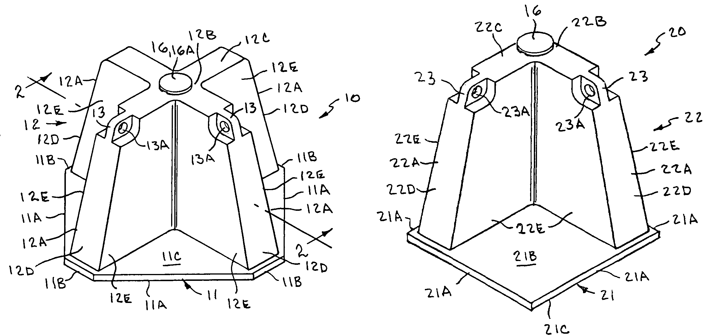
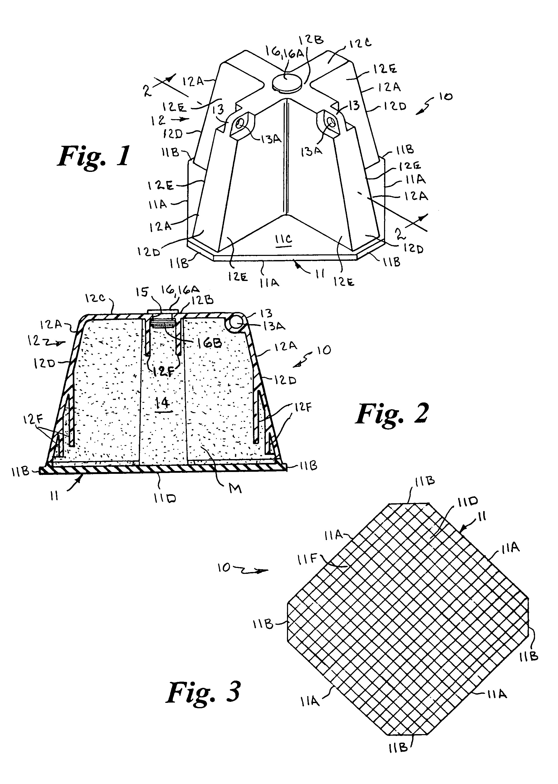
[0027]Referring to the drawings by numerals of reference, there is shown in FIGS. 1, 2 and 3, a cargo restraint device 10 in accordance with the present invention. The cargo restraint device 10 has a generally flat rectangular or octagonal base member 11 and an upright upper body portion 12. The base member 11 has four opposed parallel longer sides 11A and four opposed parallel shorter sides 11B defining the octagonal configuration. The base member 11 has a generally flat top surface 11C and a bottom surface 11D that is provided with a textured surface 11F, shown schematically in FIG. 3, which is configured to increase its frictional engagement with the surface on which it is supported and its effectiveness in preventing relative sliding movement therebetween.

[0028]In a preferred embodiment, the base member 11 is formed of rubber and the upper body portion 12 is formed of ABS material, but not limited thereto, and are bonded or otherwise secured together by conventional means to for...


PUM


Abstract

A cargo restraint device for resisting movement of cargo items on a vehicle floor or cargo bed has a generally flat octagonal or rectangular base with a slip-resistant bottom surface to be supported on the floor or bed and a top surface for receiving at least a portion of a cargo item, and a hollow upright upper body portion that can be filled with heavy material such as sand to provide weight. The upper body portion has at least two upright members extending upwardly from the base member, each having outer surfaces for abutting the cargo item, and at least one having an aperture for receiving straps to encircle a cargo item held by the device. In one embodiment four upright members intersect at a center portion in a cross-shaped configuration. In another embodiment two upright members intersect at a center portion in an L-shaped configuration.

Description

CROSS REFERENCE TO RELATED APPLICATION[0001]This application claims priority of U.S. Provisional Patent Application Ser. No. 60 / 702,903, filed Jul. 26, 2005.BACKGROUND OF THE INVENTION[0002]1. Field of the Invention[0003]This invention relates generally to load holding devices, and more particularly to a cargo restraint device for the cargo bed of a vehicle that is removably supported on the bed to engage and restrain the cargo against sliding and movement.[0004]2. Background Art[0005]The problem of sliding and movement exists when transporting items in the cargo area of vehicles, such as automobile trunks, the bed of pickup trucks, and cargo areas of SUV's, delivery trucks, boats, airplane freight areas, etc. Typically, the items that are being transported are covered or contained in cellulose cardboard or paper bags or packages, or plastic bags, which do not provide appreciable resistance against sliding relative to the surface of the cargo area. Although some vehicles provide tie...

Claims


Application Information

Patent Timeline
Patent Type & Authority Patents(United States)
IPC IPC(8): B60P7/08
CPCB60P7/0892
Inventor ARICO, JOHN JOSEPH
Owner ARICO JOHN JOSEPH
Why Eureka
Try Eureka