Blade outer seal with micro axial flow cooling system

a cooling system and blade outer seal technology, applied in the direction of machines/engines, mechanical equipment, liquid fuel engines, etc., can solve the problems of reducing the amount of energy that can be utilized for the primary purpose of providing thrust, affecting the overall engine performance, increasing the temperature and more extreme operating conditions of those parts, etc., to achieve the effect of increasing the surface area and increasing the cooling capacity

Active Publication Date: 2007-12-11
RTX CORP
View PDF6 Cites 131 Cited by
  • Summary
  • Abstract
  • Description
  • Claims
  • Application Information

AI Technical Summary

Benefits of technology

[0005]This invention is an outer air seal assembly for a turbine engine that includes a plurality of pedestals within two main cavities that produce a turbulent airflow and increase surface area resulting in an increase in cooling capacity for maintaining a hot side surface at a desired temperature.
[0007]The cavities are feed cooling air through a plurality of inlet openings. The inlet openings are disposed transverse to the gas flow. Cooling air enters the cavities and flows toward a plurality of outlets at the leading edge and a plurality of outlets along the trailing edge. Cooling air also enters the cavities through a plurality of re-supply openings that introduce additional cooling air to local areas of the cavities for maximizing cooling and heat transfer functions.
[0008]The seal segment includes axial cavities disposed adjacent axial edges that provide cooling air flow to the axial edges for preventing hot gas from seeping between adjacent seal segments. The axial cavities include dividers to isolate cooling air flow from the other cavities.
[0009]The leading edge, trailing edge and axial cavities include a plurality of pedestals that disrupt and cooling air flow to increase heat absorption capacity and to increase the surface area capable of transferring heat from the hot side. Disruption of the cooling air flow creates desirable turbulent flow from the inlets to the outlets. Turbulent air flow provides an increased heat absorption capacity. Further, the increased surface area provided by the plurality of pedestals provides an increase in heat absorption capacity. The combination of increased turbulent flow and increased surface area increases the efficiency of the cooling features allowing less cooling air flow to be utilized to provide the desired cooling of the seal segment.
[0010]Accordingly, the blade outer air seal of this invention increase cooling air effectiveness providing for the decrease in cooling air required to maintain a desired temperature of an outer air seal.

Problems solved by technology

Hot gas flow between the turbine tip and outer air seal is not transformed into mechanical energy and therefore negatively affects overall engine performance.
Cooling air is typically bleed off from other systems that in turn reduces the amount of energy that can be utilized for the primary purpose of providing thrust.
However, improvements in gas turbine engines have resulted in increased temperatures and more extreme operating conditions for those parts exposed to the hot gas flow.

Method used


Image

  • Blade outer seal with micro axial flow cooling system
  • Blade outer seal with micro axial flow cooling system
  • Blade outer seal with micro axial flow cooling system

Examples


Embodiment Construction

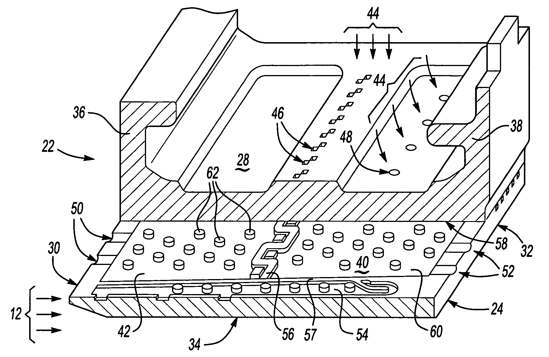
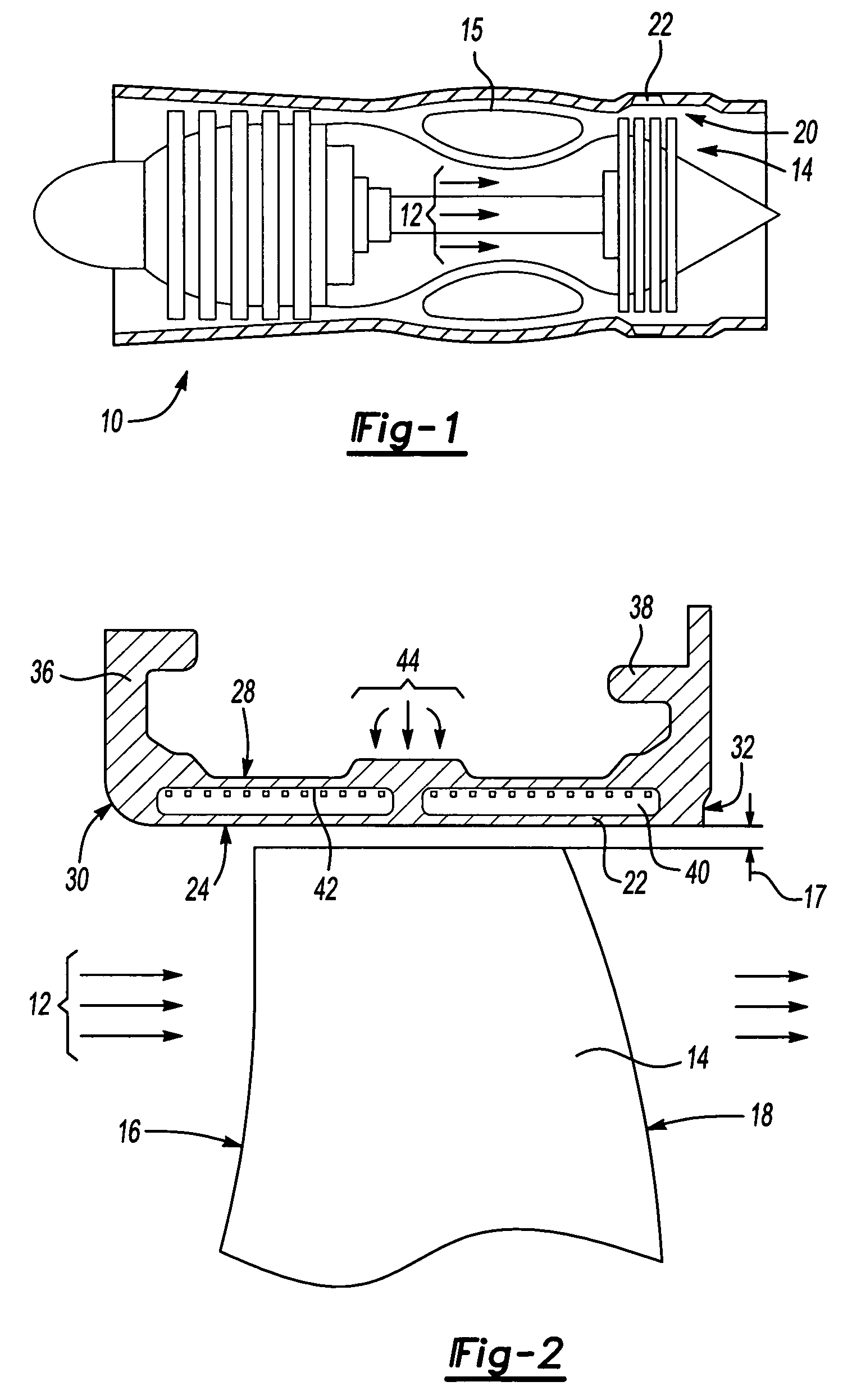
[0026]Referring to FIGS. 1 and 2, a turbine engine assembly 10 is partially and schematically shown and includes a turbine blade 14 for transforming energy from a hot combustion gas flow 12 into mechanical energy. The turbine blade 14 is an airfoil having a leading edge 16 and a trailing edge 18. Gas flow 12 is directed toward the turbine blade 14 by an exhaust liner assembly 15 as is known. The turbine blade 14 includes a tip edge 19 that is spaced apart from an outer air seal assembly 20. The outer air seal assembly 20 is spaced apart a desired clearance 17 to minimize gas flow 12 between the blade tip edge 19 and the outer air seal assembly 20. The outer air seal assembly 20 includes a plurality of outer air seal segments 22.

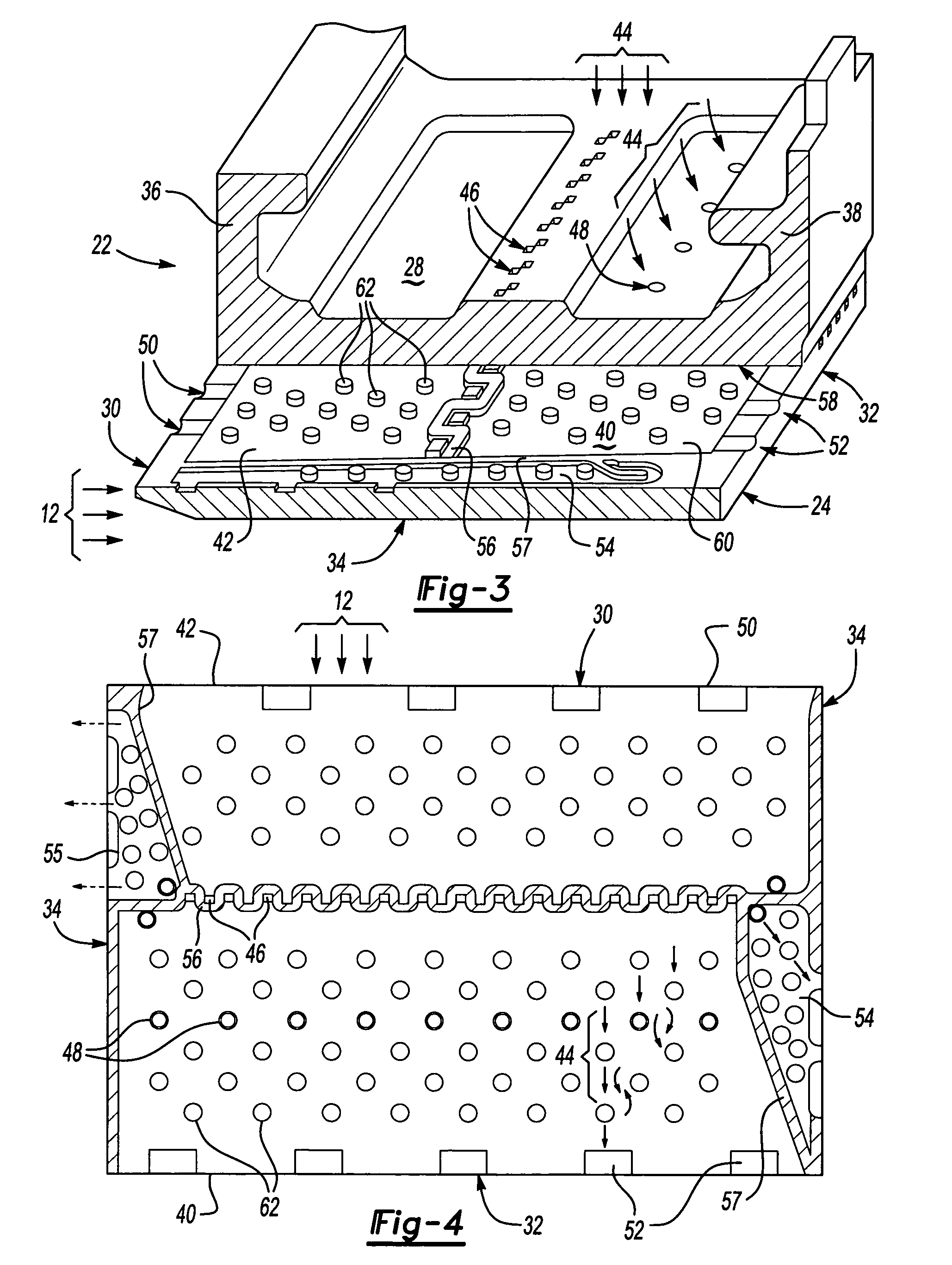
[0027]Referring to FIG. 2 the outer air seal segment 22 includes a hot side 24 that is exposed to the gas flow 12, and a back side 28 that is exposed to a supply of cooling air flow 44. The outer air seal segment 22 includes a leading edge 30, a trailing edge...


PUM


Abstract

A turbine blade outer air seal assembly includes a hot side exposed to a combustion hot gas flow, and a back side that is exposed to a supply of cooling air. The outer air seal segment includes a trailing edge cavity and a leading edge cavity separated by a divider. The cavities are feed cooling air through a plurality of inlet openings disposed transverse to the gas flow. The cooling air enters the cavities and flows toward a plurality of outlets at the leading edge and a plurality of outlets along the trailing edge. A plurality of pedestals within each of the cavities disrupts cooling air flow to increase heat absorption capacity and to increase the surface area capable of transferring heat from the hot side.

Description

BACKGROUND OF THE INVENTION[0001]This invention relates generally to a blade outer air seal for a gas turbine engine. More particularly, this invention relates to a blade outer air seal with improved cooling features.[0002]A gas turbine engine includes a compressor, a combustor and a turbine. Compressed air is mixed with fuel in the combustor to generate an axial flow of hot gases. The hot gases flow through the turbine and against a plurality of turbine blades. The turbine blades transform the flow of hot gases into mechanical energy to rotate a rotor shaft that drives the compressor. A clearance between a tip of each turbine blade and an outer air seal is preferably controlled to minimize flow of hot gas therebetween. Hot gas flow between the turbine tip and outer air seal is not transformed into mechanical energy and therefore negatively affects overall engine performance. Accordingly, the clearance between the tip of the turbine blade and the outer air seal is closely controlled...

Claims


Application Information

Patent Timeline
Patent Type & Authority Patents(United States)
IPC IPC(8): F01D5/14
CPCF01D11/08F01D25/12F05D2260/2214F05D2260/2212F05D2260/22141F05D2240/11F01D11/02F01D5/20F01D11/00
Inventor ROMANOV, DMITRIYDRAKE, JEREMY
Owner RTX CORP
Why Eureka
Try Eureka