
Branch vessel graft design and deployment method

a branch vessel and graft technology, applied in the field of endoluminal medical devices and procedures, can solve the problems of complexity and space/volume requirements of the delivery system

Active Publication Date: 2007-12-11
MEDTRONIC VASCULAR INC
View PDF31 Cites 114 Cited by
  • Summary
  • Abstract
  • Description
  • Claims
  • Application Information

AI Technical Summary

Benefits of technology

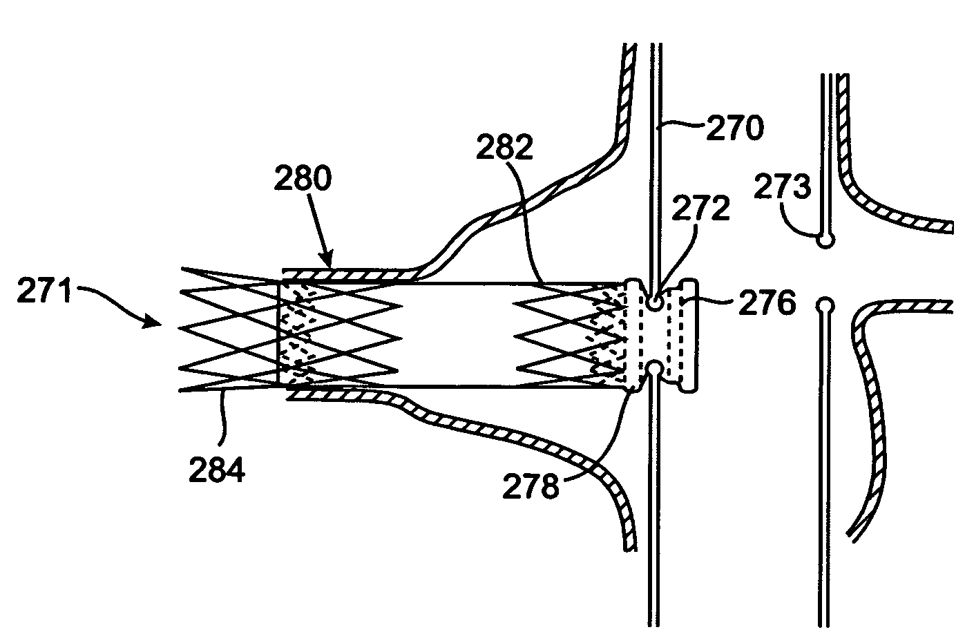
The present invention provides an improved design for connecting a stent graft to a branch vessel at the location of an aneurysm in the main vessel. A branch graft design is used that includes a tubular branch graft and two self-expanding support rings. The first support ring is attached to the proximal end of the branch graft, while the second support ring is attached to the distal end of the graft. The branch graft is connected to the main graft through a side opening with a flush reinforcing ring or flange. The support rings can be sewn onto the inside or outside of the tubular branch graft and are made of nitinol. The invention also includes a method for deploying the main stent graft and branch vessel graft and a branch graft delivery system. The technical effects of the invention include improved connection between the stent graft and branch vessel, reduced risk of complications, and improved outcomes.

Problems solved by technology

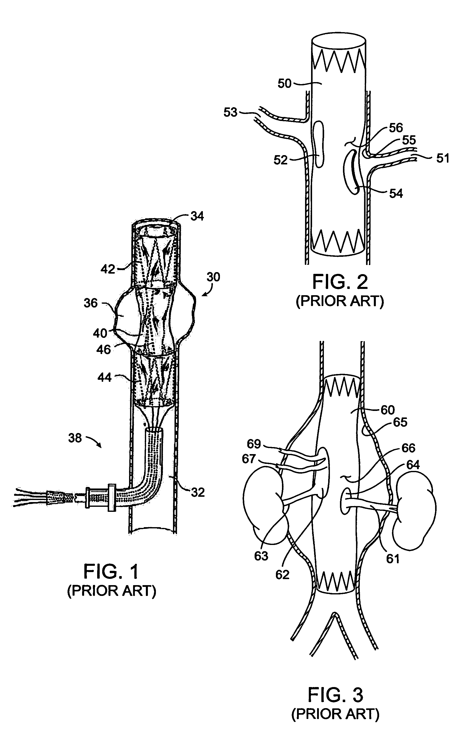
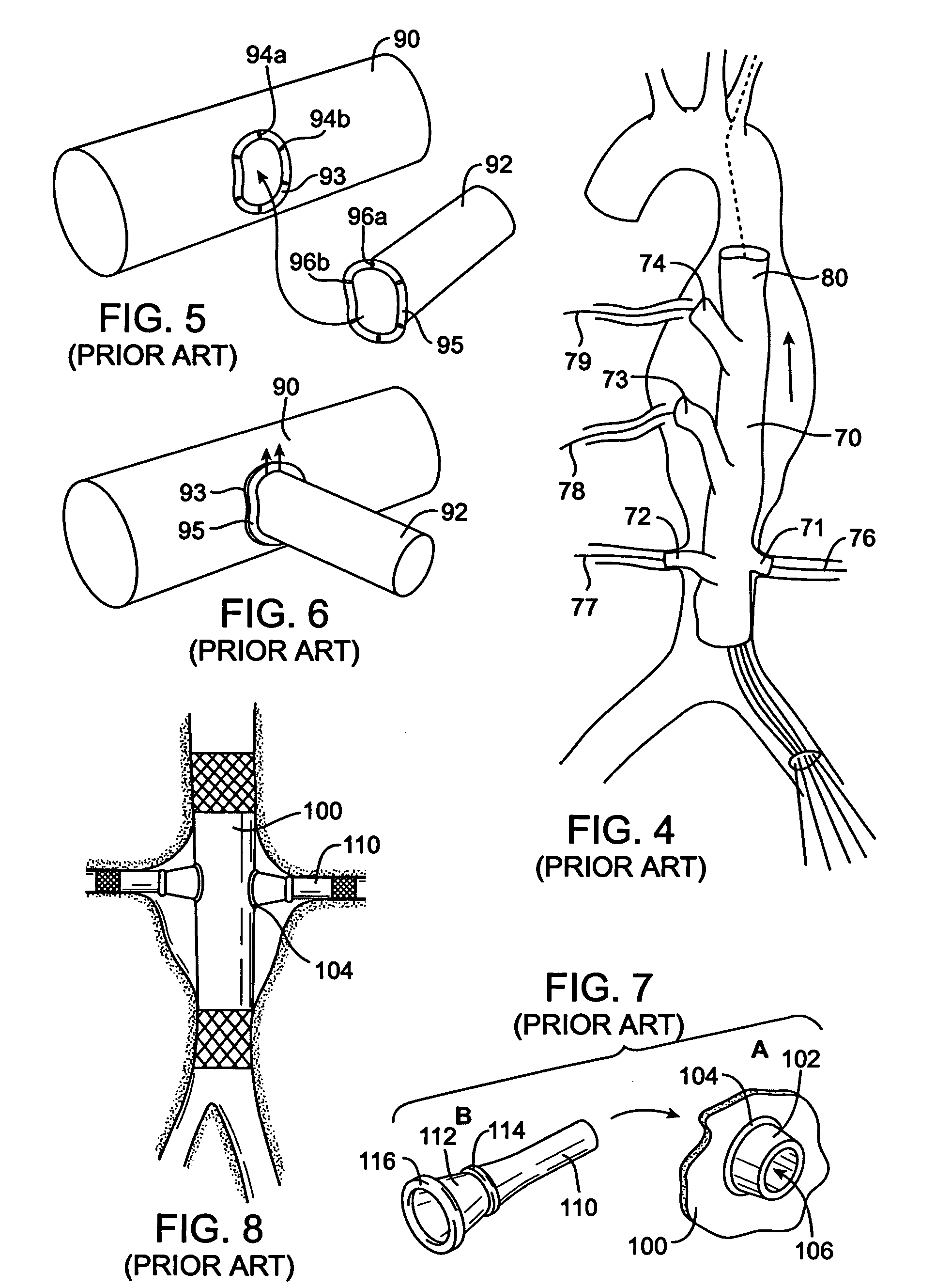
These examples of prior art devices to facilitate flow from an aneurysmal portion of the aorta into branch vessels show the complexity and space / volume requirements needed in the delivery system to deliver and accurately align such prior art systems.

Method used


Image

  • Branch vessel graft design and deployment method
  • Branch vessel graft design and deployment method
  • Branch vessel graft design and deployment method

Examples


Embodiment Construction

[0034]FIG. 9 shows a balloon expandable branch graft stent system 120 in accordance with the invention. A catheter having a catheter inner member (inner tube) 122 extends from a proximal end 124 to a distal end 126 of the catheter. A balloon 128 is located at the distal end 126 of the catheter and bonded to the catheter inner member 122 in a balloon to catheter member distal bond region 132. The proximal end of the balloon 128 is bonded at a balloon to outer member proximal bond region 130 to an outer member 144 that provides a coaxial annular lumen between its inner surface and the outer surface of the catheter inner member 122. The balloon expandable stent 134 compressed around the balloon 128 is positioned between a stent location proximal marker band 140 and a stent location distal marker band 142 both mounted on the catheter inner member 122. A tubular graft material 138 is sewn or bonded to the outside of the stent in a stent to graft material bonding section 136. Tubular graf...


PUM


Abstract

A branch graft stent system includes a tubular primary graft having a branch graft opening which when deployed is located in alignment with a side branch vessel emanating from the primary vessel in which a branch graft is deployed. A connector (flange) member forms a perimeter of the branch graft opening and is constructed so that the connector member is substantially flush with the wall of the tubular primary graft. The tubular branch graft has a first expandable ring and a second expandable ring spaced apart from each other as part of a connection section located at a proximal end of the tubular branch graft. The first expandable ring, the second expandable ring, and graft or other material spaced between the first expandable ring and the second expandable ring when engaged with the perimeter of the branch graft opening of the primary graft, the assembly forms a flexible sealed connection between the primary graft and branch graft lumens to continue to exclude the aneurysm while providing a conduit for blood flow to the branch vessel. A distal end of the branch graft can be anchored by a balloon expandable or a self-expanding stent to the wall of the branch vessel beyond the aneurysm.

Description

FIELD OF THE INVENTION[0001]This invention relates generally to endoluminal medical devices and procedures, and more particularly to branch vessel grafts secondarily attached to a main vessel stent graft using a system of rings coupled to the branch graft for a sealed branch vessel graft connection to a main stent graft.BACKGROUND OF THE INVENTION[0002]Prostheses for implantation in blood vessels or other similar organs of the living body are, in general, well known in the medical art. For example, prosthetic vascular grafts formed of biocompatible materials (e.g., Dacron or expanded, porous polytetrafluoroethylene (PTFE) tubing) have been employed to replace or bypass damaged or occluded natural blood vessels. A graft material supported by framework is known as a stent graft. In general, the use of stent grafts for treatment or isolation of vascular aneurysms and vessel walls which have been thinned or thickened by disease (endoluminal repair or exclusion) are well known. Many sten...

Claims


Application Information

Patent Timeline
Patent Type & Authority Patents(United States)
IPC IPC(8): A61F2/06A61F2/82A61F2/94
CPCA61F2/07A61F2/856A61F2/94A61F2/954A61F2230/0054A61F2002/821A61F2/89A61F2/90A61F2220/0075A61F2002/075
Inventor WATSON, JAMES R.
Owner MEDTRONIC VASCULAR INC
Learn More