RF plasma reactor having a distribution chamber with at least one grid

Inactive Publication Date: 2007-12-11
OERLIKON SOLAR AG (TRUEBBACH)
View PDF30 Cites 11 Cited by
  • Summary
  • Abstract
  • Description
  • Claims
  • Application Information

AI Technical Summary

Benefits of technology

[0023]It further must be considered that by the inventively provided rim portion of the wall, distant from the periphery of the plate, an inlet channel to the plasma discharge space is formed. If there is installed an electric potential difference between the plate and the wall, then this electric potential will also

Problems solved by technology

A further drawback of this known arrangement is primarily its low response time.
Thus, if during processing one wants to change the gas composition or outflow rate, such change, considered in the plasma discharge space, will occur during a rather uncontrolled transient phase with large time constants up to reaching the desired stable, newly established gas composition and/or outflow rate.
This especially considering the

Method used


Image

  • RF plasma reactor having a distribution chamber with at least one grid
  • RF plasma reactor having a distribution chamber with at least one grid
  • RF plasma reactor having a distribution chamber with at least one grid

Examples


Example

DETAILED DESCRIPTION OF THE DRAWINGS

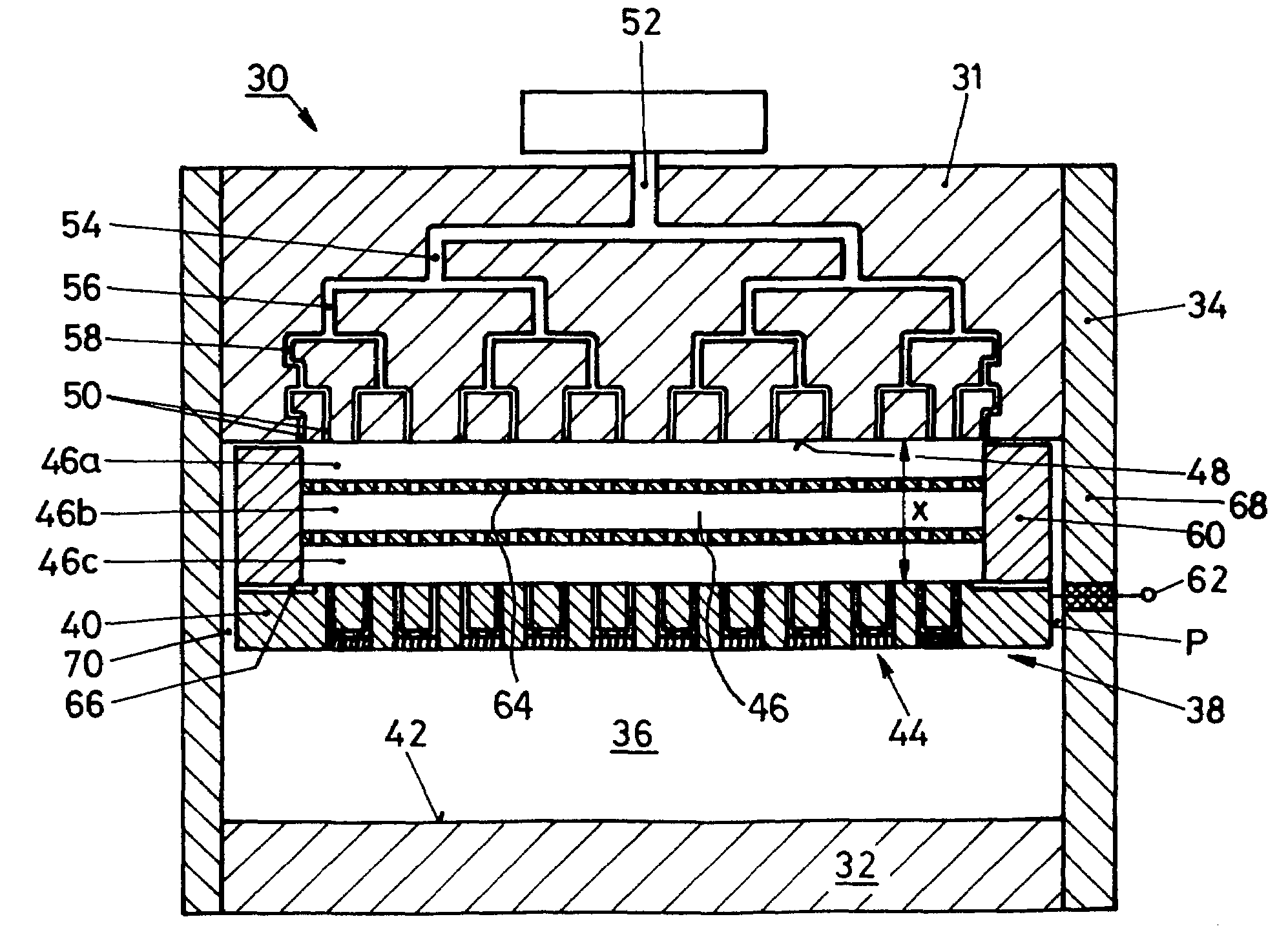
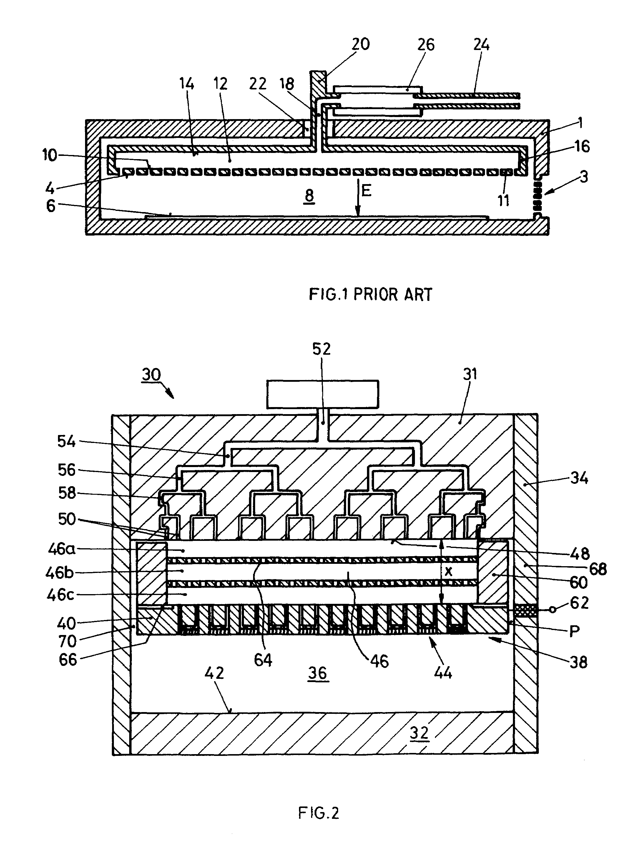
[0031]In FIG. 2 there is schematically shown an RF plasma reactor of a preferred mode. Therein, all the four sets of features which per se resolve the inventively set object are combined, and whereby, as was said before, each of these sets of features per se is considered inventive.

[0032]The RF reactor 30 comprises an upper wall 31, bottom wall 32 and lateral wall 34. A first electrode surface 38 is formed by the surface of a metallic plate 40 and points towards the plasma discharge space 36. In this embodiment the second plasma discharge electrode is formed especially by the metallic upper surface 42 of the bottom wall 32.

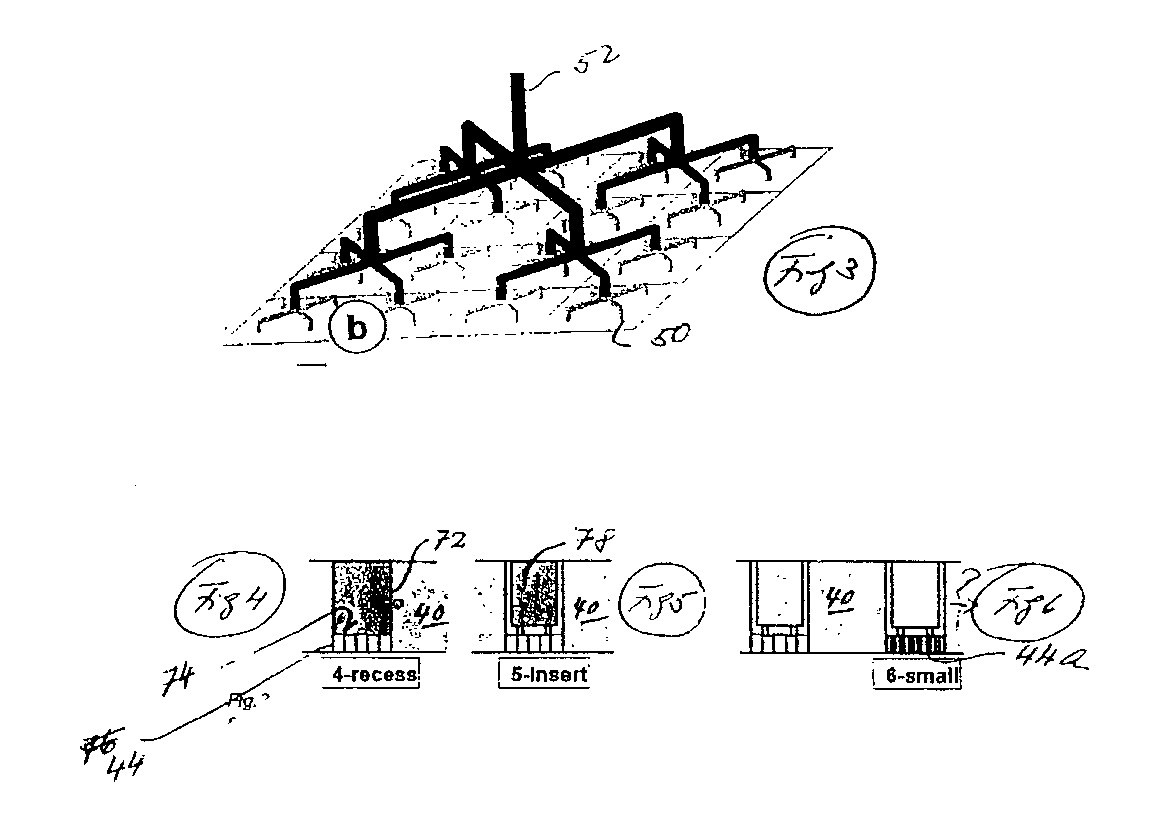
[0033]In plate 40 there is provided a multitude of openings 44 pointing towards the plasma discharge space 36 and from a distribution chamber 46. A gas inlet arrangement 48 feeds gas into distribution chamber 46, wherefrom it is dispatched to the plasma discharge space 36 through the openings 44.

[0034]Preferred layout of the gas...


PUM


Abstract

A plasma reactor has a reactor vessel and a pair of electrodes in the form of spaced apart and oppositely disposed metallic surfaces defining therebetween a plasma discharge space. At least one of the metallic surfaces is the surface of a metallic plate having a plurality of gas feed openings extending through the metallic surface towards said discharge space and from a distribution chamber extending along the plate opposite the discharge space. The distribution chamber has a wall opposite and distant from the plate and includes a gas inlet arrangement with a plurality of gas inlet openings distributed along the wall and connected to one or more gas feed lines to the reactor. A gas flow resistant coefficient between the one or more gas feed lines and at least a predominant portion of the connected inlet openings are at least substantially equal.

Description

[0001]This application is a continuation of application Ser. No. 09 / 559,408, filed Apr. 26, 2000 now U.S. Pat. No. 6,502,530.BACKGROUND AND SUMMARY OF THE INVENTION[0002]The present invention is generically directed on improvements with respect to so-called shower head gas inlet technique into a plasma discharge space of a plasma reactor operated with a plasma which is electrically fed by RF, RF plus DC or pulsed RF. Thereby, it is directed to parallel plate reactors, where RF energy is coupled to the discharge space via a pair of electrodes in a capacitance plate-like arrangement, in contrary to other reactors, where the discharge energy is introduced via microwave coupling or via induction field.[0003]Such capacitive-coupling plasma reactors are commonly used for exposing at least one substrate at a time to the processing action of a plasma glow discharge. A wide variety of such processes are known and used to modify the nature of the substrate's surfaces. Depending on the process...

Claims


Application Information

Patent Timeline
IPC IPC(8): H05H1/24H01L21/306C23C16/00H05H1/46B01J19/08B01J19/24C03C23/00C23C16/44C23C16/455C23C16/50C23C16/509H01J37/32H01L21/205H01L21/302H01L21/3065
CPCC23C16/455C23C16/45561C23C16/45565C23C16/509C23C16/507H01J37/32082H01J37/3244H01J37/32623H01J37/32697C23C16/5096H01L21/205
Inventor TURLOT, EMMANUELCHEVRIER, JEAN-BAPTISTESCHMITT, JACQUESBARREIRO, JEAN
Owner OERLIKON SOLAR AG (TRUEBBACH)
Why Eureka
Try Eureka