Switchable voltage converter

a voltage converter and switch technology, applied in the direction of electric discharge lamps, electric variable regulation, instruments, etc., can solve the problem of low complexity of inductors, and achieve the effect of reducing the complexity of switched voltage converters compared to the prior ar

Inactive Publication Date: 2007-12-11
PATENT TREUHAND GESELLSCHAFT FUER ELECTRIC GLUEHLAMPEN M B H
View PDF7 Cites 3 Cited by
  • Summary
  • Abstract
  • Description
  • Claims
  • Application Information

AI Technical Summary

Benefits of technology

[0009]In the case of ripple current compensation, the series circuit comprising a second inductor and a capacitor is connected in parallel with the electronic switch of the boost converter. High-frequency current (ripple current) flows largely in the second inductor, while only little high-frequency current, in comparison to the second inductor, flows in a first inductor, which is coupled to the input of the voltage converter, as a result of which radio interference is reduced. Complete compensation of the high-frequency current in the first inductor is possible owing to a magnetic coupling between the first inductor and the second inductor. The two inductors can be dimensioned such that each inductor only needs to have half the maximum energy storage capacity of the single inductor in a boost converter without ripple current compensation. The additional complexity for inductors is thus low in the case of a boost converter having ripple current compensation compared to the boost converter without ripple current compensation.
[0011]Only a single switch is required to disconnect the booster diode. In the two modes, in each case only one diode is out of operation, and the two inductors are used in optimum fashion in both modes. The complexity of the switched voltage converter compared to the prior art is therefore considerably reduced and is even only slightly greater than the complexity for the unswitched separate converters.

Problems solved by technology

The additional complexity for inductors is thus low in the case of a boost converter having ripple current compensation compared to the boost converter without ripple current compensation.

Method used


Image

  • Switchable voltage converter
  • Switchable voltage converter
  • Switchable voltage converter

Examples


Embodiment Construction

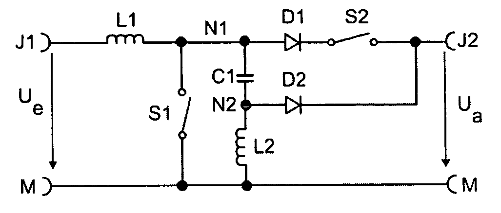
[0017]FIG. 1 shows one exemplary embodiment of a switchable voltage converter according to the invention. A series circuit comprising a first inductor L1 and an electronic switch S1 is connected between an input terminal J1 and a reference potential M, a first node N1 being formed at the connection point. The voltage converter can be fed by an energy source, which produces an input voltage Ue at J1, between the input terminal J1 and the reference potential M. The energy source is generally a rectified system voltage. If appropriate, a filter is also interposed for the purpose of reducing radio interference or to counteract overvoltage.

[0018]A series circuit comprising a first capacitor C1 and a second inductor L2 is connected in parallel with the electronic switch S1, a second node N2 being formed at the connection point between the first capacitor C1 and the second inductor L2. This series circuit implements the abovementioned ripple current compensation. In order to improve compen...


PUM


Abstract

A voltage converter, whose topology can be switched over between a boost converter and a SEPIC. The boost converter has ripple current compensation. As a result, the inductors used can be utilized in optimum fashion. A thyristor which is protected against breakdown triggering by a negative gate voltage is used as the changeover switch.

Description

FIELD OF THE INVENTION[0001]The invention relates to a switchable voltage converter which can be used in pulsed power supplies. The invention also relates to an operating device for operating lamps using a voltage converter according to the invention.BACKGROUND OF THE INVENTION[0002]The topologies of boost converter and SEPIC (single-ended primary inductance converter) are generally known in pulsed power supplies. In particular in the case of two-stage operating devices for discharge lamps, these types of converter are widely used in the first stage. The first stage provides power factor correction and makes available an intermediate circuit voltage, while a second stage generally produces a high-frequency AC voltage to be supplied to the discharge lamp. An electronic switch, which switches at a high frequency compared to a system frequency, provides the clock pulse in the two pulsed power supplies.[0003]The document WO 02 / 41480 (Chang) discusses the respective advantages and disadv...

Claims


Application Information

Patent Timeline
Patent Type & Authority Patents(United States)
IPC IPC(8): H05B37/02
CPCH01J61/125H02M3/158H02M2003/1557H02M3/1557H02M3/155
Inventor STORM, ARWED
Owner PATENT TREUHAND GESELLSCHAFT FUER ELECTRIC GLUEHLAMPEN M B H
Why Eureka
Try Eureka