Electronic package and method of cooling electronics

a technology of electronic components and electronic components, applied in the direction of electrical apparatus contruction details, semiconductor/solid-state device details, lighting and heating apparatus, etc., can solve problems such as electrical circuit failure, adverse effects, and increase in temperatur

Active Publication Date: 2007-12-11
DELPHI TECH IP LTD
View PDF10 Cites 79 Cited by
  • Summary
  • Abstract
  • Description
  • Claims
  • Application Information

AI Technical Summary

Problems solved by technology

The generated thermal energy within the electronic package generally results in increased temperature.
Excessive heat build-up within certain electronic packages may lead to adverse effects including electrical circuit failure.
While many conventional electronic cooling approaches dissipate some of the thermal energy away from the electronic device, such approaches generally do not offer optimal heat dissipation.
The resultant heat dissipation realized in conventional electronic packages often results in large package size and reduced power constraints.

Method used


Image

  • Electronic package and method of cooling electronics
  • Electronic package and method of cooling electronics
  • Electronic package and method of cooling electronics

Examples


first embodiment

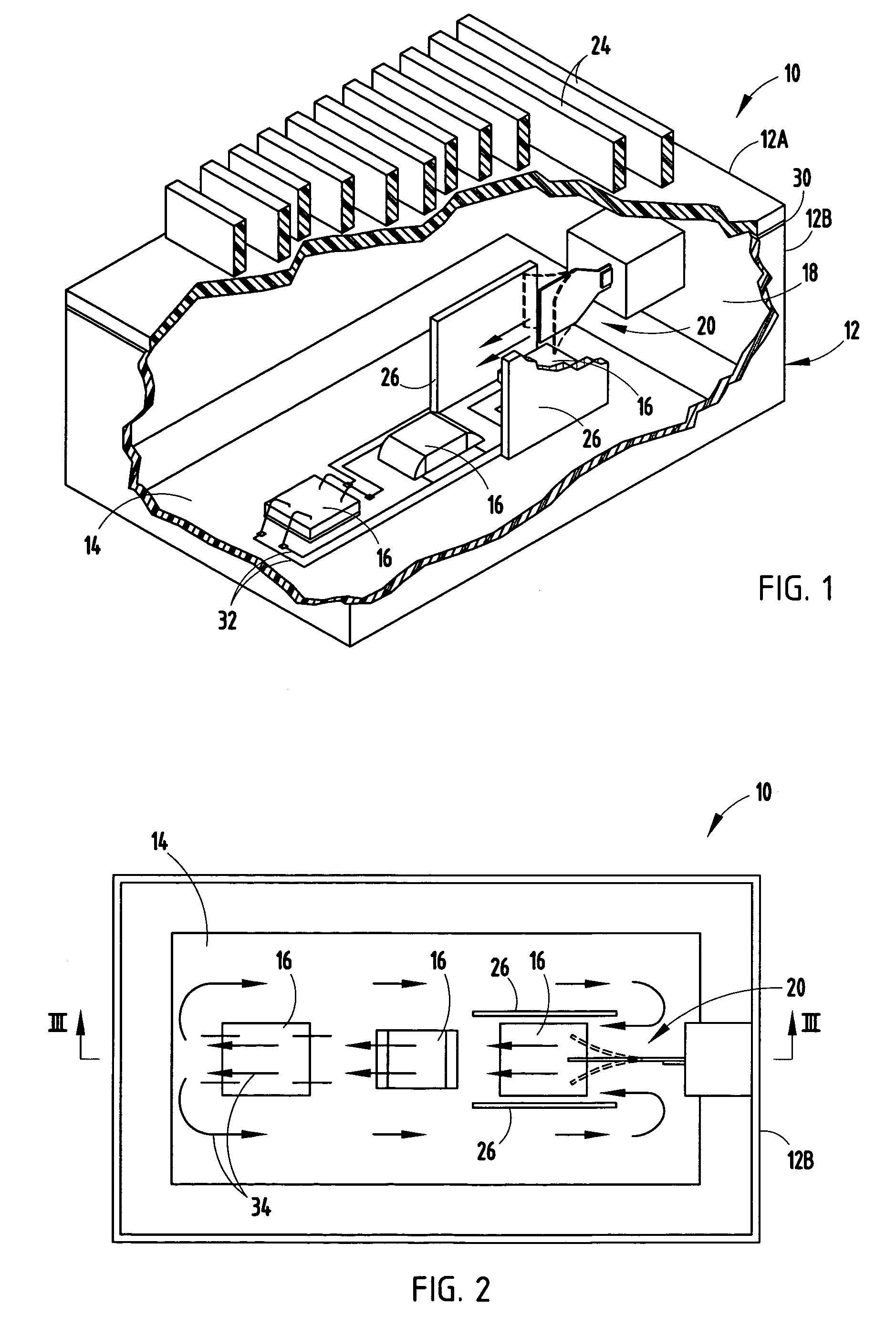
[0017]Referring to FIGS. 1-3, an electronic package 10 is generally illustrated according to the present invention. The electronic package 10 includes a thermally conductive housing 12 having a base 12B made up of four generally rectangular side walls and a bottom wall and a cover 12A generally defined by a top wall. The cover 12A is sealed via a seal (e.g., gasket) 30 and fasteners (e.g., threaded screws) (not shown) to the base 12B to define a sealed enclosure that prevents ingress and egress of fluid. The housing 12 may be made of a diecast metal that is thermally conductive to transmit thermal energy (heat) from within the enclosure of housing 12 to the outside ambient environment.

[0018]Disposed within the enclosure of housing 12 is a substrate 14, such as a printed circuit board, shown located on the interior surface of the bottom wall. The substrate 14 may be made of low temperature co-fired ceramic (LTCC), an organic material such as FR4, a metal such as stainless steel, or a...

second embodiment

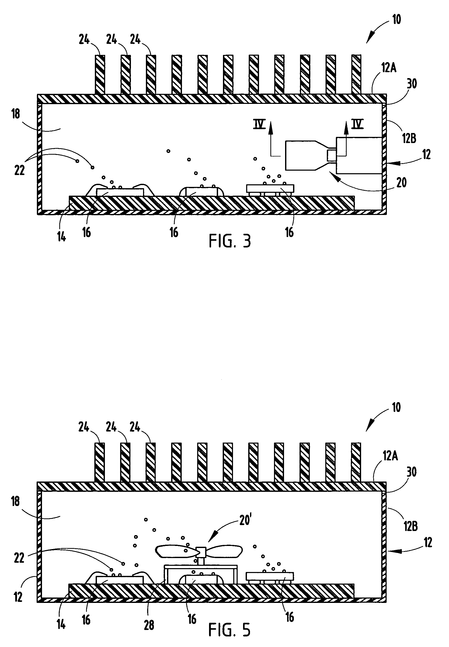
[0029]Referring to FIG. 5, the electronic package 10 is further illustrated having a microrotary fan 20′ according to a The microrotary fan 20′ is shown mounted on a support frame 28 above an electronic device 16. The microrotary fan 20′ is a submersible rotary blade fan that circulates dielectric fluid 18 within the sealed enclosure such that fluid 18 passes in contact with electronic device(s) 16 to provide cooling of the electronic device(s) 16. The thermal energy from electronic device(s) 16 is thereby effectively transferred to the dielectric fluid 18, then to the housing 12 and to the outside surrounding environment.

[0030]Accordingly, the electronic package 10 of the present invention employs one or more cooling fluid circulators 20 or 20′ for circulating dielectric fluid 18 within housing 12 to pass in heat transfer relationship with one or more electronic devices 16 to cool the electronic devices 16. By employing a circulated dielectric fluid 18, such as liquid, in heat tra...


PUM


Abstract

An electronic package having circulated submersed cooling fluid and method are provided. The electronic package has a housing defining a sealed enclosure and electronic devices located in the housing. The electronic devices have thermal emitting electrical circuitry. A dielectric fluid, such as a liquid, is located in the housing in heat transfer relationship with the electronic devices. A fluid circulator, such as a piezo fan, is located in the housing in contact with the dielectric liquid for circulating the dielectric liquid to cool the electronic devices.

Description

TECHNICAL FIELD[0001]The present invention generally relates to the cooling of heat generating electronics and, more particularly, to an electronic package having thermal energy cooling for dissipating heat away from the electronic device(s).BACKGROUND OF THE INVENTION[0002]Electronic packages typically employ semiconductor devices, such as flip chips, Insulated Gate Bipolar Transistor (IGBT) chips and other electronics. Electronic packages, such as those used in electronic control modules (ECM), generally contain electrical circuitry often implemented as integrated circuitry including electronic components, such as transistors and resistors. The electrical circuitry conducts electrical current which, in turn, typically generates thermal energy (i.e., heat).[0003]Electronic packages are often equipped with a housing for protecting the electrical circuit components from damage due to moisture and contact. The generated thermal energy within the electronic package generally results in...

Claims


Application Information

Patent Timeline
Patent Type & Authority Patents(United States)
IPC IPC(8): H05K7/20F28F7/00H01L23/34
CPCH01L23/44H01L23/473H05K7/20236H05K7/20909H01L2924/09701H01L2224/48091H01L2924/1305H01L2924/13055H01L2224/16225H01L2924/00014H01L2924/00
Inventor BERLIN, CARL W.CHENGALVA, SURESH K.BRANDENBURG, SCOTT D.MYERS, BRUCE A.
Owner DELPHI TECH IP LTD
Why Eureka
Try Eureka