Raindrop sensor

a sensor and raindrop technology, applied in vehicle maintenance, vehicle cleaning, instruments, etc., can solve the problems of reducing the amount of light received, degrading the accuracy of raindrop detection,

Active Publication Date: 2007-12-18
DENSO CORP
View PDF14 Cites 136 Cited by
  • Summary
  • Abstract
  • Description
  • Claims
  • Application Information

AI Technical Summary

Benefits of technology

[0011]To achieve the objective of the present invention, there is provided a raindrop sensor for sensing a raindrop attached to a transparent panel. The raindrop sensor includes a light-emitting element, a light-receiving element and a light guide body. The light-emitting element faces the transparent panel, wherein the light-emitting element emits light toward the transparent panel. The light-receiving element faces the transparent panel, wherein the light-receiving element receives the light emitted by the light-emitting element. The light guide body, which is mounted on the transparent panel, includes an input lens, an input side dividing surface, an output lens and an output side dividing surface. The input lens is formed on an input side of the light guide body, wherein the input lens is divided into a plurality of input lens segments, which are displaced from each other in a direction parallel to an optical axis of the input lens. The input side dividing surface divides adjacent two of the plurality of input lens segments and is flat. The output lens is formed on an output side of the light guide body, wherein the output lens is divided into a plurality of output lens segments, which are displaced from each other in a direction parallel to an optical axis of the output lens. The output side dividing surface divides adjacent two of the plurality of output lens segments and is flat. The input lens collimates the light, which is emitted by the light-emitting element, to form an input side collimated light beam. The output lens receives the collimated light beam, which is collimated by the input lens and is reflected by a reference surface of the transparent panel, to which the raindrop attaches. The output lens converges the reflected collimated light beam toward the light-receiving element so that the light-receiving element receives the reflected collimated light beam. An intersection between an imaginary extension of the input side dividing surface and an imaginary extension of the output side dividing surface is located on the reference surface of the transparent panel.

Problems solved by technology

As a result, accuracy for detecting raindrops is degraded at the part of the raindrop-sensing region, which receives the decreased amount of light.

Method used


Image

  • Raindrop sensor
  • Raindrop sensor
  • Raindrop sensor

Examples


first embodiment

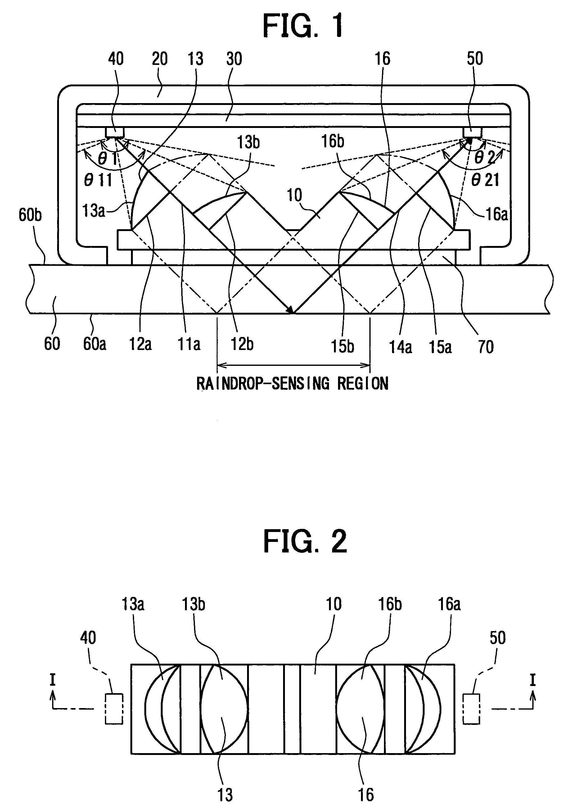
[0022]A first embodiment of the present inventions will be described with reference to the accompanying drawings. A raindrop sensor is adopted for a wiper automatic control device, which is mounted on an exterior wall surface (or a reference surface) 60a of a windshield (or a transparent panel) 60 of a car. Besides the windshield, the transparent panel may include a transparent sunroof panel, a rear window, a side window or the like of the car. The raindrop sensor is mounted on an interior wall surface 60b of the windshield 60 correspondingly to a wiper area of the wiper. The raindrop sensor optically detects raindrops, which attach to the wiper area, to output a signal to the wiper automatic control device. FIG. 1 is a schematic view of a light guide body taken along line I-I in FIG. 2 for showing a raindrop sensor mounted on the interior wall surface 60b of the windshield 60 of the car according to the present invention. FIG. 2 is a top view for showing an arrangement of a light g...

second embodiment

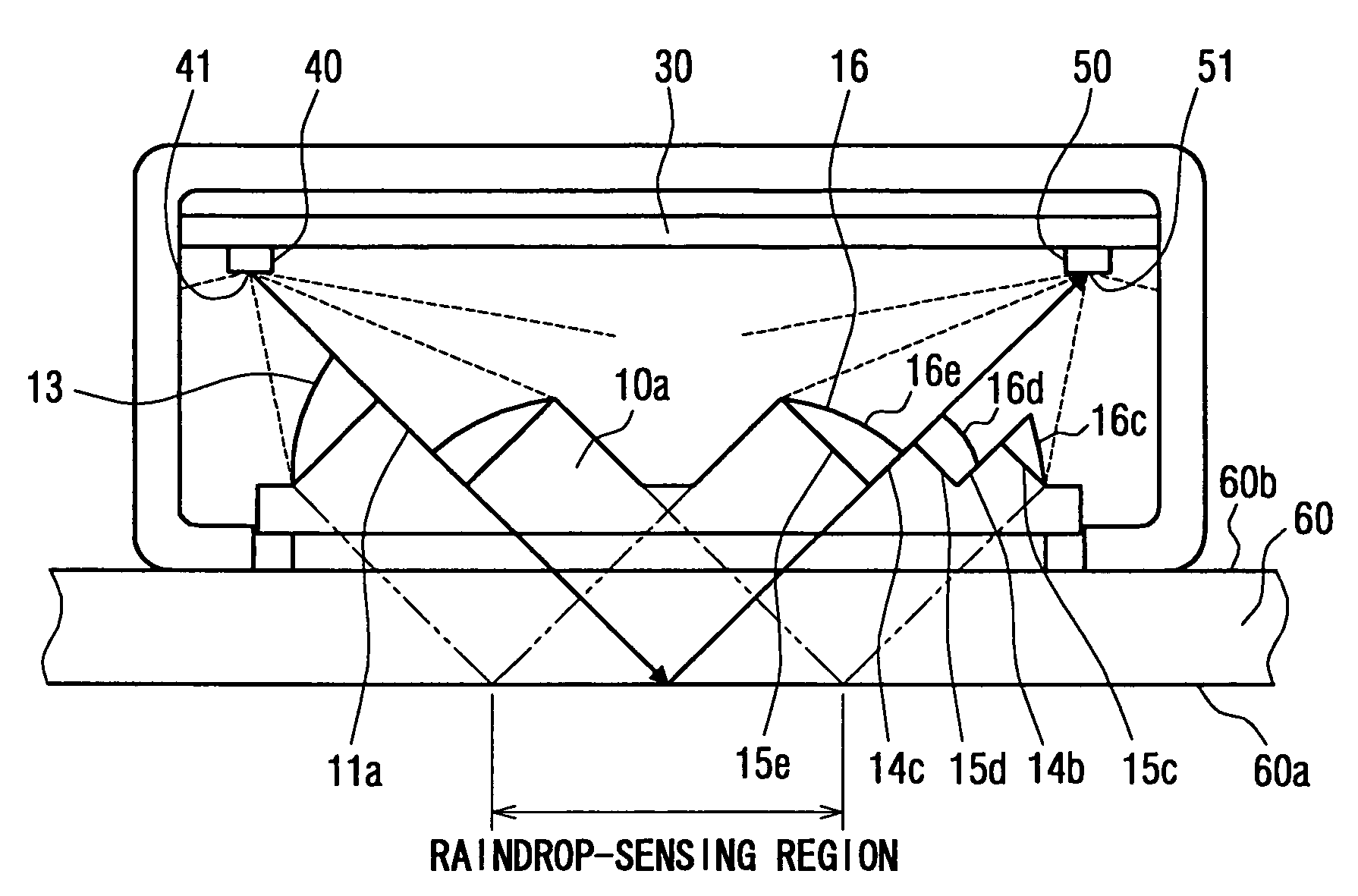
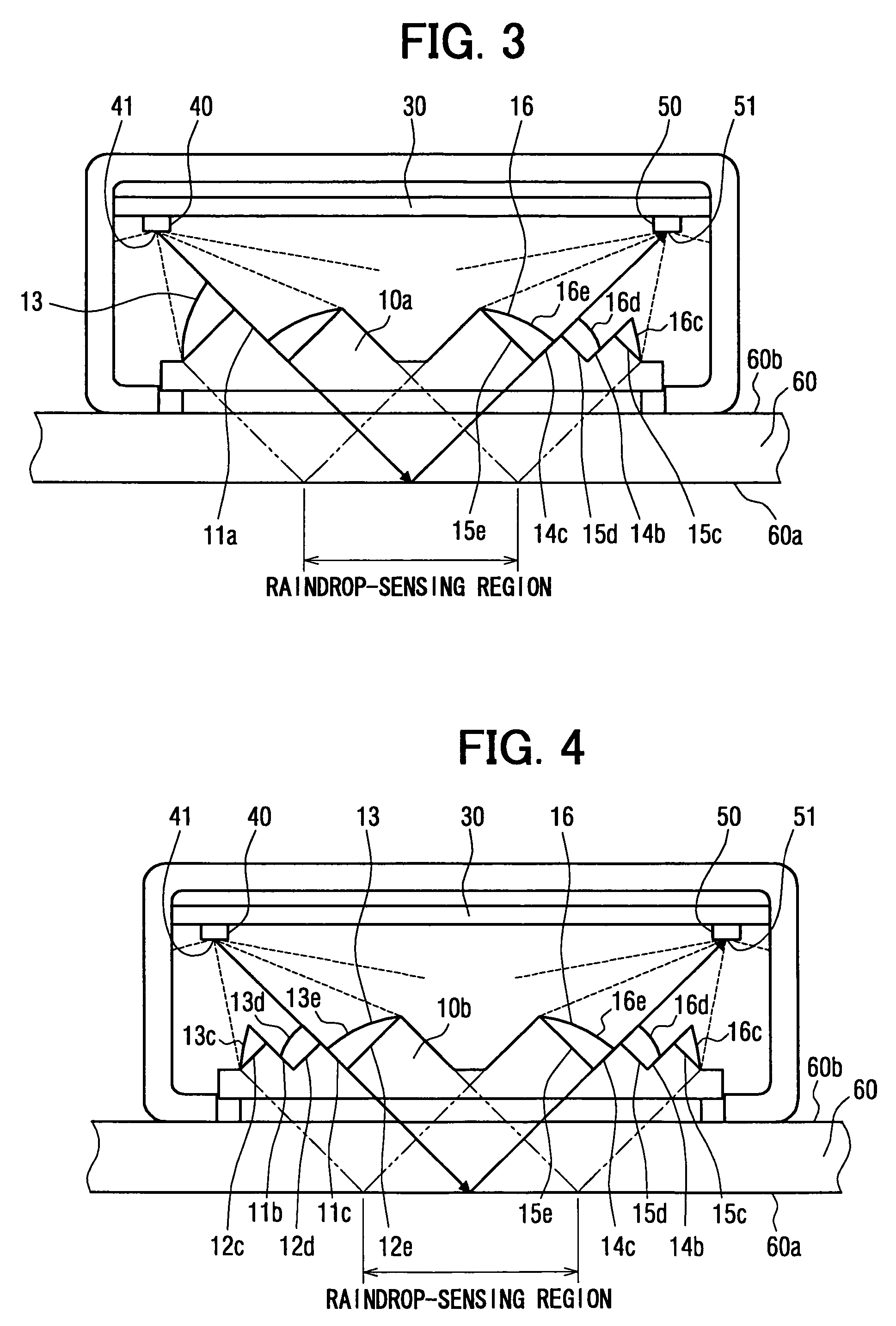
[0064]A second embodiment of the present invention will be described with reference to FIG. 3 and FIG. 4. Similar components of the raindrop sensor of the second embodiment, which is similar to the components of the raindrop sensor of the first embodiment, will be indicated by the same numerals. In the second embodiment, three or more of inclined planes are formed on at least one of the input side and output side. FIG. 3 is a sectional view of the raindrop sensor mounted on the interior wall surface 60b of the windshield 60 of the car according to the second embodiment. FIG. 4 is a sectional view of the raindrop sensor mounted on the interior wall surface 60b of the windshield 60 of the car according to a modification of the second embodiment.

[0065]As shown in FIG. 3, the light guide body 10a includes three output side inclined planes 15c-15e and two output side dividing surfaces 14b, 14c. Output side planoconvex lens segments 16c-16e are formed on the corresponding output side incl...

third embodiment

[0072]A comparative example will be described with reference to FIG. 5. Similar components of the raindrop sensor of the third embodiment, which is similar to the components of the raindrop sensor of the first and / or second embodiments, will be indicated by the same numerals. In the comparative example four input side inclined planes and four output side inclined planes are formed. FIG. 5 is a sectional view of the raindrop sensor mounted on the interior wall surface 60b of the windshield 60 of the car according to the third embodiment. As shown in FIG. 5, the light guide body 10c includes four input side inclined planes 12f-12i and three input side dividing surfaces 11d-11f on the input side. Also, the light guide body 10c includes four output side inclined planes 15f-15i and three output side dividing surfaces 14d-14f. Input side planoconvex lens segments 13f-13i are formed on the corresponding input side inclined planes 12f-12i. Output side planoconvex lens segments 16f-16i are f...


PUM

PropertyMeasurementUnit
angle θ1aaaaaaaaaa
transparentaaaaaaaaaa
curvaturesaaaaaaaaaa

Abstract

A raindrop sensor includes a light-emitting element, a light-receiving element and a light guide body. The light-emitting element and the light-receiving element face a transparent panel. The light guide body, which is mounted on the transparent panel, includes an input lens, an input side dividing surface, an output lens and an output side dividing surface. The input lens collimates light emitted by the light-emitting element to form an input side collimated light beam. The output lens receives the collimated light beam, which is collimated by the input lens and is reflected by a reference surface of the transparent panel, to which the raindrop attaches. The output lens converges the reflected collimated light beam toward the light-receiving element. An intersection between an imaginary extension of the input side dividing surface and an imaginary extension of the output side dividing surface is located on the reference surface of the transparent panel.

Description

CROSS REFERENCE TO RELATED APPLICATION[0001]This application is based on and incorporates herein by reference Japanese Patent Application No. 2004-255971 filed on Sep. 2, 2004.BACKGROUND OF THE INVENTION[0002]1. Field of the Invention[0003]The present invention relates to a raindrop sensor, which is specifically suitable for a vehicle wiper automatic control device.[0004]2. Description of Related Art[0005]Conventionally, a raindrop sensor for detecting raindrops, which attach to a vehicle windshield and the like, is known (see Unexamined Japanese Patent Publication No. 2001-66246 corresponding to U.S. Pat. No. 6,507,015). The raindrop sensor shown in the Unexamined Japanese Patent Publication No. 2001-66246 is mounted on an interior wall of the windshield 200, and optically detects raindrop attachment as shown in FIG. 9. The raindrop sensor mainly includes a light guide body 140, planoconvex lenses 120, 130, planoconvex lens segments 150, 160, light-emitting elements 100, 110 and a ...

Claims


Application Information

Patent Timeline
Patent Type & Authority Patents(United States)
IPC IPC(8): G01N21/49B60S1/08G01N21/17
CPCB60S1/0822G01N21/55G01N21/41B60S1/0837B60S1/08B60S1/04B60S1/06
Inventor ISHIKAWA, JUNICHI
Owner DENSO CORP
Why Eureka
Try Eureka