Using position-sensitive detectors for wavelength determination

a position-sensitive detector and wavelength determination technology, applied in the direction of optical radiation measurement, interferometric spectrometry, instruments, etc., can solve the problems of only limited resolution of a position-sensitive detector, poor wavelength discrimination capability, and relatively expensive components, so as to improve the wavelength selectivity of the wedge-shaped etalon

Active Publication Date: 2007-12-18
XEROX CORP
View PDF25 Cites 89 Cited by
  • Summary
  • Abstract
  • Description
  • Claims
  • Application Information

AI Technical Summary

Benefits of technology

[0016]Exemplary embodiments of a coating with laterally varying transmission properties may be a Fabry-Perot cavity with a laterally varying thickness (e.g., a wedge-shaped etalon) or a cavity with laterally varying index of refraction. The wedge-shaped etalon has a wedge-shaped transmissive cavity, having a thickness that varies across the surface of the detector and being positioned adjacent to at least one reflective layer. The wedge-shaped etalon has a transmission function that varies across the surface of the detector according to the thickness of the transmissive cavity. Therefore, a shift in the wavelength of the input light causes a shift in the position of the transmitted spot on the photosensitive detector. Use of a wedge-shaped etalon substantially improves the wavelength selectivity over a linear variable filter, such as described in Gat.
[0017]The reflective layers on the transmissive cavity may be a plurality of thin films, with thicknesses and indices of refraction that are chosen to form a distributed Bragg reflector (DBR). Using highly reflective Bragg reflectors further improves the wavelength selectivity of the wedge-shaped etalon.

Problems solved by technology

However, the device described in Gat suffers from using relatively expensive components, and having rather poor wavelength discrimination capabilities.
This is particularly true for any wavelength range where Si-based devices cannot be used.
The resolution of a position-sensitive detector is only limited by the accuracy with which a differential current can be measured.

Method used


Image

  • Using position-sensitive detectors for wavelength determination
  • Using position-sensitive detectors for wavelength determination
  • Using position-sensitive detectors for wavelength determination

Examples


Embodiment Construction

[0039]FIG. 5 shows a first exemplary embodiment of the chip-size wavelength detector 1000, according to this invention. As shown in FIG. 5, the chip-size wavelength detector 1000 includes two components, a film with laterally varying transmission properties 100 and a position-sensitive detector 300. The wavelength detector 1000 may be used to determine the absolute wavelength of a monochromatic source, or it may be used to measure a wavelength shift of a source away from a nominal wavelength.

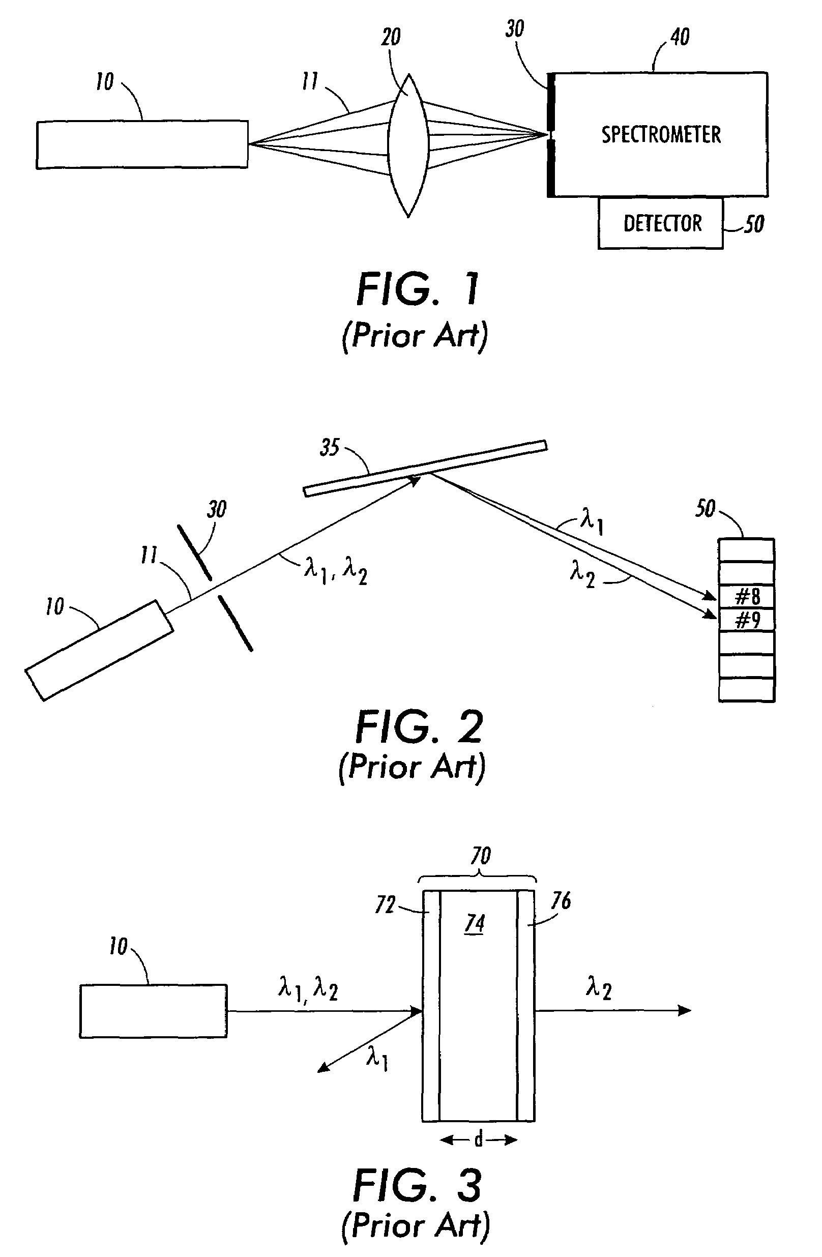
[0040]The position-sensitive detector 300 may be a device which outputs a signal (e.g., a normalized current difference) which is proportional to the location of a light spot on the surface of the detector. For example, the position-sensitive detector 300 will output a different signal level, depending on whether a light spot falls on location #8 or location #9 on the position-sensitive detector 300.

[0041]The film with laterally varying transmission properties may be variable thickness etalon 10...


PUM


Abstract

A chip-size wavelength detector includes a film with laterally varying transmission properties and a position-sensitive detector. The film transmits a different wavelength as a function of lateral position across the film. The position of a spot of light transmitted through the film will shift, depending on the wavelength of the light. The shift is measured by the position-sensitive detector.

Description

BACKGROUND OF THE INVENTION[0001]1. Field of Invention[0002]This invention is directed to techniques that use position-sensitive detectors, such as in measuring wavelength of light, in measuring wavelength shift of light, or in producing a chip-size wavelength detector.[0003]2. Description of Related Art[0004]Spectrometers and wavelength shift detectors are widely used in scientific, academic and industrial applications to measure the various wavelengths of multi-colored light. Known spectrometers use a wavelength dispersive means, such as a prism or grating, to separate components of the multi-colored light according to the wavelengths of the components. The intensity of the wavelength components is then measured by a photodetector.[0005]Wavelength shift detectors may also use wavelength dispersive means. However, instead of measuring intensity as a function of wavelength, they generally measure a shift in wavelength of a single frequency source away from a nominal value. Often spe...

Claims


Application Information

Patent Timeline
Patent Type & Authority Patents(United States)
IPC IPC(8): G01B9/02
CPCG01J9/0246G01J3/26
Inventor KIESEL, PETERSCHMIDT, OLIVERWOLST, OLIVER
Owner XEROX CORP
Why Eureka
Try Eureka