Control circuit having two-level under voltage lockout threshold to improve the protection of power supply

a control circuit and voltage lockout threshold technology, applied in the protection circuit field of power supply, can solve the problem that the supply capacitor will therefore start to discharge, and achieve the effect of improving the protection of the power supply

Active Publication Date: 2007-12-18
SEMICON COMPONENTS IND LLC
View PDF5 Cites 41 Cited by
  • Summary
  • Abstract
  • Description
  • Claims
  • Application Information

AI Technical Summary

Benefits of technology

[0003]The invention provides a control circuit including two levels of under voltage lockout threshold to improve the protection of the power supply. The control circuit includes a switching circuit, a protection circuit and a detection circuit. The switching circuit is coupled to an output terminal of the power supply to generate a switching signal for regulating the output of the power supply. The protection circuit is developed to disable the switching signal in response to the fault condition. The detection circuit will generate a start signal and an on / off signal to turn on / off the circuits of the control circuit in accordance with the input voltage of the control circuit. The detection circuit includes a first under-voltage lockout threshold and a second under-voltage lockout threshold.
[0004]An input terminal of the control circuit is connected to a supplied capacitor to supply the power to the control circuit. The supplied capacitor is charged through a start resistor for the start-up. Once the input voltage reaches a start-up voltage, the detection circuit will generate the start signal and the on / off signal to start the switching signal. After that, the supplied capacitor is charged by a transformer of the power supply. If a fault condition is occurred, the protection circuit will disable the switching signal, and the supplied capacitor will therefore start to discharge. When the input voltage is discharged lower than the first under-voltage lockout threshold, the circuits of the control circuit are shut down by the detection circuit to consume lower power and increase the discharge time of the supplied capacitor. Furthermore, once the input voltage is discharged lower than the second under-voltage lockout threshold, the control circuit will enable the start- up again by the detection circuit. During the discharge period from the first under-voltage lockout threshold to the second under-voltage lockout threshold, the switching of the control circuit is off and the discharge time is increased which reduces of the switching duty cycle and improves the protection of the power supply.

Problems solved by technology

If a fault condition is occurred, the protection circuit will disable the switching signal, and the supplied capacitor will therefore start to discharge.

Method used


Image

  • Control circuit having two-level under voltage lockout threshold to improve the protection of power supply
  • Control circuit having two-level under voltage lockout threshold to improve the protection of power supply
  • Control circuit having two-level under voltage lockout threshold to improve the protection of power supply

Examples


Embodiment Construction

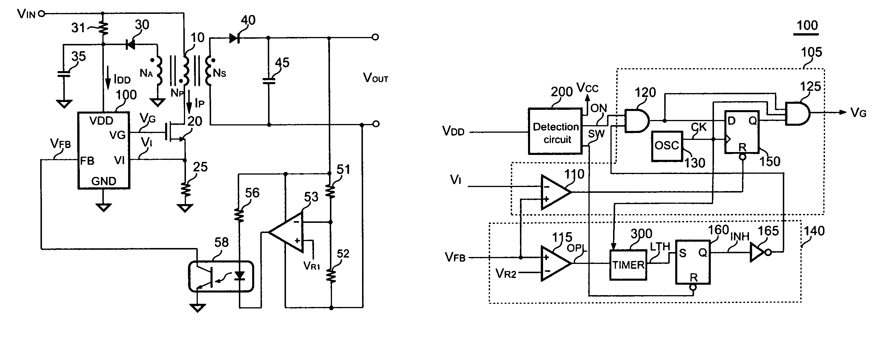
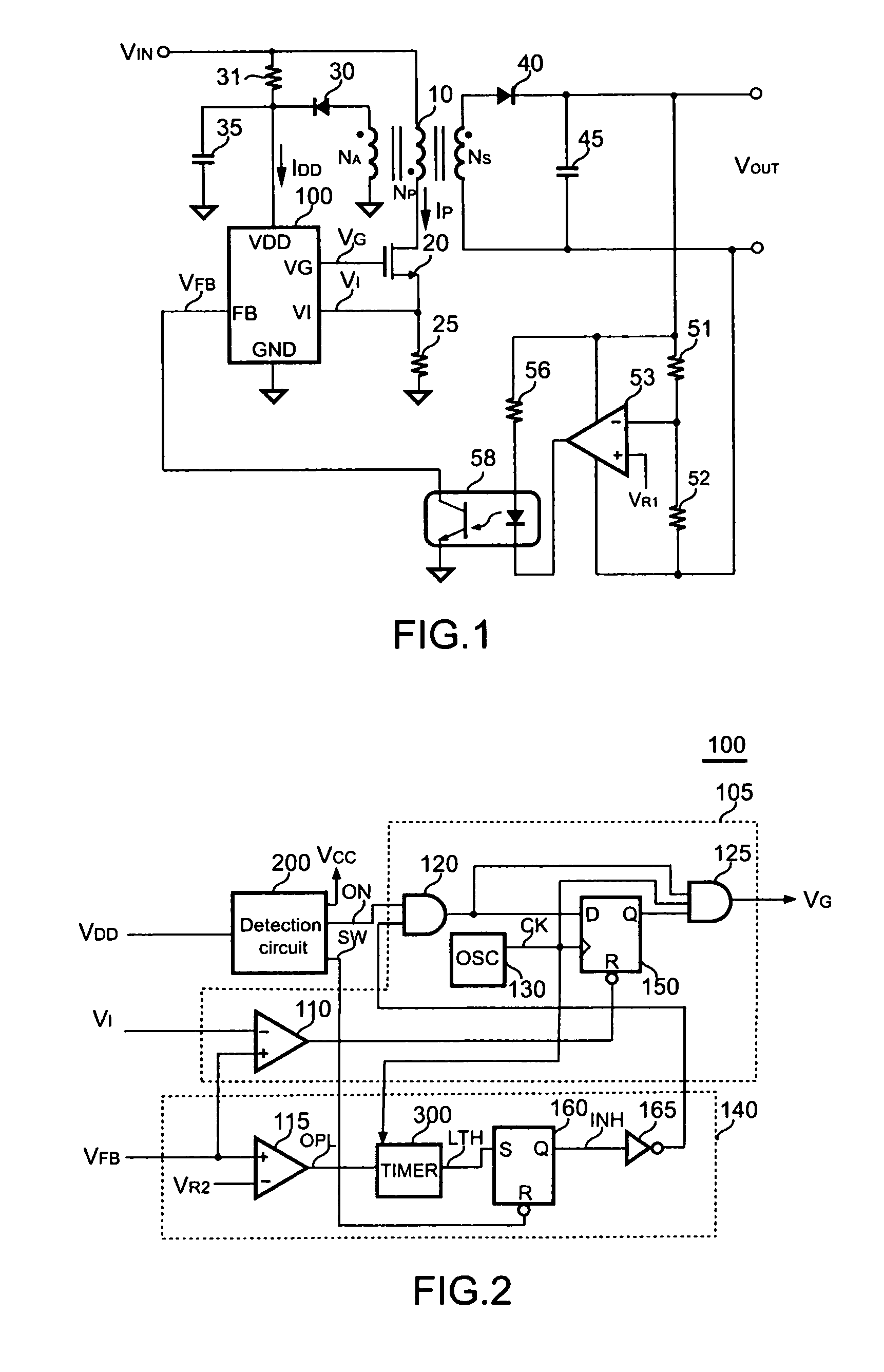
[0012]FIG. 1 shows a schematic of a power supply. A transformer 10 includes a primary winding NP, a secondary winding NS and an auxiliary winding NA. A terminal of the primary winding NP is coupled to an unregulated voltage VIN. A transistor 20 is connected from another terminal of the primary winding NP to a ground through a current sense resistor 25. The current sense resistor 25 is used to convert a switching current IP of the transformer 10 to a sense voltage VI. A start resistor 31 is connected from the unregulated voltage VIN to charge a supplied capacitor 35. The supplied capacitor 35 is further connected to an input terminal VDD of a control circuit 100 for supplying the power to the control circuit 100. Once the input voltage VDD is charged up to a start up voltage of the control circuit 100, the control circuit 100 will start to operate.

[0013]A ground terminal GND of the control circuit 100 is coupled to the ground. A current sense terminal VI of the control circuit 100 re...


PUM


Abstract

The invention presents a switching power control circuit including two levels of under voltage lockout to improve the protection of the power supply. An input terminal of control circuit is connected to a supplied capacitor to supply the power of the control circuit. The supplied capacitor is charged through a start resistor for the start-up. Once the input voltage reaches a start-up voltage, the control circuit will start the operation. After that, the power is further supplied from a transformer of the power supply. If a fault condition is occurred, the switching of the control circuit will be stop and the supplied capacitor will be discharged. When the input voltage is discharged lower than a first under-voltage lockout threshold, the circuits of control circuit are shut down to consume lower power. Furthermore, once the input voltage is discharged lower than a second under-voltage lockout threshold, the control circuit will enable the start-up again. During the discharge period from the first under-voltage lockout threshold to second under-voltage lockout threshold, the switching of the control circuit is off and the discharge time is increased which reduces of the switching duty cycle and improves the protection of the power supply.

Description

FIELD OF THE INVENTION[0001]The present invention relates to power supply and more specifically relates to the protection circuit of power supply.BACKGROUND OF THE INVENTION[0002]Power supplies are used to provide regulated output from an unregulated power source. For the sake of safety reasons, a protection circuit must be provided to protect the power supply itself and the system it power. A limited power output is strictly required for a power supply during fault conditions such as overload, short circuit and feedback open loop. The object of the present invention is to provide a control circuit to reduce the output power during the power supply protection.SUMMARY OF THE INVENTION[0003]The invention provides a control circuit including two levels of under voltage lockout threshold to improve the protection of the power supply. The control circuit includes a switching circuit, a protection circuit and a detection circuit. The switching circuit is coupled to an output terminal of t...

Claims


Application Information

Patent Timeline
Patent Type & Authority Patents(United States)
IPC IPC(8): H02H7/122H02M3/335G05F1/40
CPCH02H7/1222H02H3/243
Inventor YANG, TA-YUNGHUANG, WEI-HSUAN
Owner SEMICON COMPONENTS IND LLC
Why Eureka
Try Eureka