Cutting insert and cutting tool

a cutting tool and insert technology, applied in the field of metal cutting tools, can solve the problems of occupying considerable space near the center of the tool body, occupying considerable space at the working end of the tool, and occupying considerable space in the tool body

Active Publication Date: 2007-12-25
ISCAR LTD
View PDF22 Cites 7 Cited by
  • Summary
  • Abstract
  • Description
  • Claims
  • Application Information

AI Technical Summary

Benefits of technology

[0086]The present invention facilitates increasing the number of cutting inserts positioned on the cutting portion peripheral surface of a given tool having given diameter, while simultaneously providing for precise positioning of each cutting insert at the same cutting diameter, by associating each cutting insert with a dedicated adjusting mechanism positioned radially inwardly relative thereto and accessible therethrough. By providing for insert adjustment through the cutting insert, the cutting inserts can be positioned close to each other, thereby increasing the number of cutting inserts which can be employed in the given tool, thus contributing to better productivity while maintaining precise positioning accuracy and repeatability of the cutting inserts.
[0087]Although the present invention has been described to a certain degree of particularity, it should be understood that various alterations and modifications could be made without departing from the scope of the invention as hereinafter claimed.

Problems solved by technology

However, adjusting mechanisms require installation space in the tool.
However, the insert adjustment and clamping mechanisms occupy considerable space at the working end of the tool.
However, the adjusting mechanism in U.S. Pat. No. 4,425,063 precludes radial adjustment of the cutting edge position of the cutting insert.
Each cutting insert is clamped by a clamping jaw, and is urged radially outwardly by an adjusting screw positioned radially inwardly therefrom, thereby occupying considerable space near the center of the tool body, and limiting the number of cutting inserts which can be installed.

Method used


Image

  • Cutting insert and cutting tool
  • Cutting insert and cutting tool
  • Cutting insert and cutting tool

Examples


Embodiment Construction

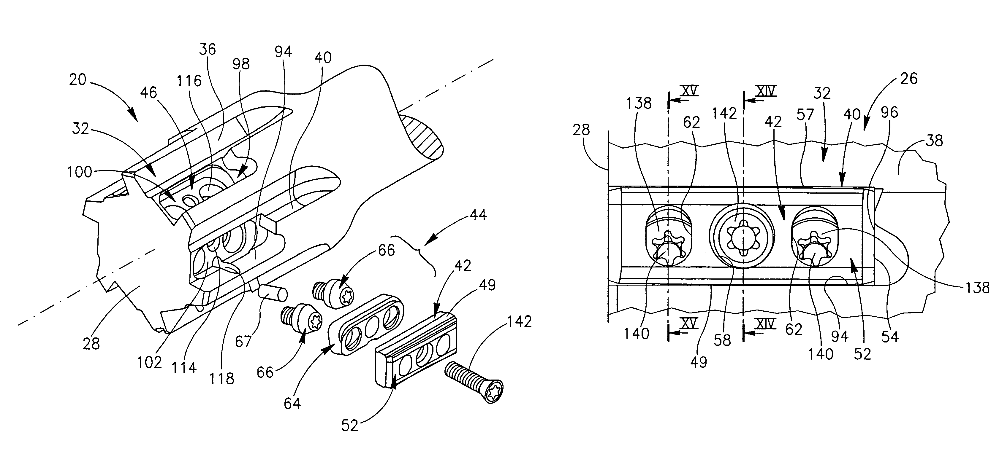
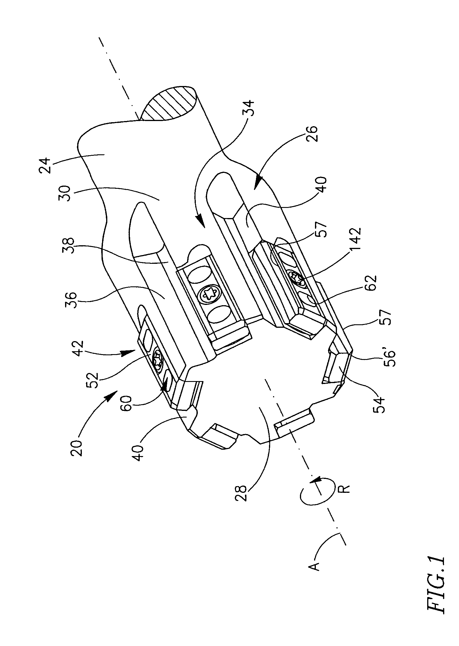
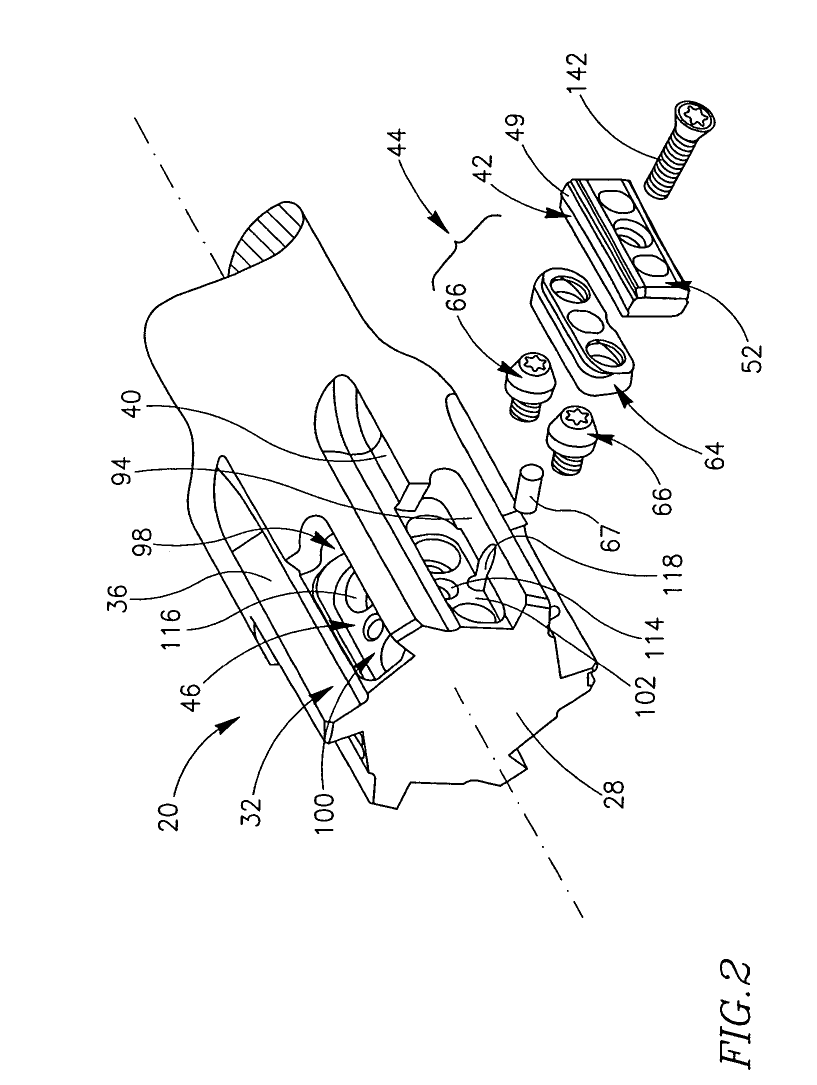
[0062]Attention is first drawn to FIG. 1. A reamer 20 of a first embodiment of the present invention comprises a tool body 22 of a generally cylindrical shape having an axis of rotation A defining a front-to-rear direction and a direction of rotation R. The tool body 22 comprises a rear tool shank 24 and a front tool cutting portion 26. The tool cutting portion 26 comprises a tool front face 28 and a cutting-portion peripheral surface 30 extending axially rearwardly therefrom. It should be noted that directional terms appearing throughout the specification and claims, e.g. “front”, “rear”, “leading”, “trailing”, etc., (and derivatives thereof) are for illustrative purposes only, and are not intended to limit the scope of the appended claims.

[0063]The cutting-portion peripheral surface 30 comprises a plurality of flutes 32 extending axially rearwardly from the tool front face 28 and inwardly from the cutting-portion peripheral surface 30. The flutes 32 define therebetween mounting po...


PUM

PropertyMeasurementUnit
wedge plate angleaaaaaaaaaa
wedge intermediate angleaaaaaaaaaa

Abstract

A metal cutting tool is provided with at least one cutting insert mounted in an insert pocket in communication with an adjusting mechanism, the cutting insert comprising at least one insert adjusting slot extending between two opposing major faces thereof and opening out to each major face at an adjusting aperture and the adjusting mechanism comprising at least one adjusting member having an adjusting member top face underlying the cutting insert while being visible and accessible therethrough.

Description

FIELD OF THE INVENTION[0001]The present invention relates to a metal cutting tool having an adjusting mechanism for adjusting the position of a cutting insert secured in the cutting tool relative thereto, and to a cutting insert for securing in the metal cutting tool, and in particular to a metal cutting tool having a plurality of such cutting inserts mounted on a periphery thereof.BACKGROUND OF THE INVENTION[0002]Such metal cutting tools require accurate positioning of an operative cutting edge relative to the tool. Precise adjustment of the operative cutting edge position is particularly important for finishing operations. However, adjusting mechanisms require installation space in the tool. Therefore, the adjusting mechanism should preferably be dimensionally compact so as to occupy as little space as possible in the cutting tool. This requirement is especially important in tools used for metal removal inside cavities of the work-piece, such as boring or reaming tools, because th...

Claims


Application Information

Patent Timeline
Patent Type & Authority Patents(United States)
IPC IPC(8): B23D77/00B23CB23D77/04
CPCB23D77/044B23B2205/12B23B2260/056B23C2200/367B23D2277/76Y10T408/858Y10T408/8593Y10T407/2222Y10T407/1914Y10T407/193Y10T407/23
Inventor HECHTELIEZER, OLEG
Owner ISCAR LTD
Why Eureka
Try Eureka