
Granular material weighing hoppers containing pinch values or flipping-type hoppers

Inactive Publication Date: 2007-12-25
YAMATO SCALE CO LTD
View PDF36 Cites 13 Cited by
  • Summary
  • Abstract
  • Description
  • Claims
  • Application Information

AI Technical Summary

Benefits of technology

[0007]By making use of a combination weigher for powdery or granular materials, which essentially have continuous weighed values, it becomes unnecessary to carry out the small quantity charging in supplying a powdery or granular material to the scale units, so that the weighing speed can be improved considerably. In addition, because the powdery or granular material that equates to a target weight of the entire scale can be charged in parts into a plurality of scale units and, moreover, the charging of the powdery or granular material can be performed simultaneously to each of the scale units, the weighing speed can be also improved. Furthermore, it becomes unnecessary to carry out the switchover from the large quantity charging to the small quantity charging, eliminating the need for a control device therefor and, thus, it becomes possible to reduce the cost of the scale.
[0009]In a powdery- or granular-material weighing apparatus of the present invention, each of the scale units constitutes a combination weigher, so that a variation in the weights of the powdery or granular material charged in respective scale units does not cause a problem even if it occurs, and a variety of low-cost powdery- or granular-material supplying means other than the feeders that are, as in conventional cases, capable of finely adjusting the charging quantity of a powdery or granular material can be adopted.
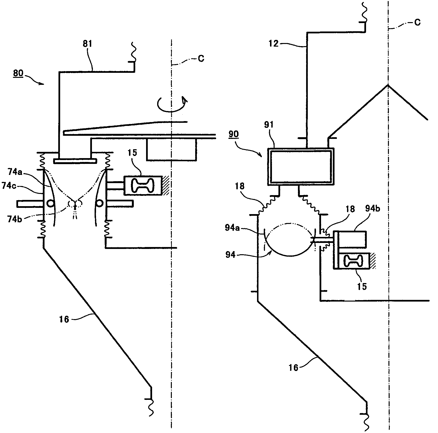
[0010]In addition, a weighing hopper for weighing a material to be weighed may comprise a cylindrical portion and a pinch valve for opening / closing a lower portion of the cylindrical portion, or may comprise a receiving container that receives the material to be weighed and flips upside down. By adopting a weighing hopper with such a configuration, it is possible to prevent leakage of the powdery or granular material from the gate, which is caused by the use of the gate used in the conventional combination weigher, in the case where the powdery or granular material is a fine powdery material with a high flowability.

Problems solved by technology

However, in the foregoing method (1), in which the charging weight in the large quantity charging is increased, overshoot occurs when the flow rate changes at the switchover from the large quantity charging to the small quantity charging, as shown in FIG. 13, resulting in a situation in which the target weight is assumed to be reached and the small quantity charging is not carried out.
Likewise, in the foregoing method (2), in which the flow rate in the large quantity charging is increased, overshoot also occurs when the flow rate changes at the switchover from the large quantity charging to the small quantity charging, resulting in a situation in which the weighed values obtained finally will be less than the target weight.
Further, there is a drawback in that a control for the switchover from the large quantity charging to the small quantity charging is necessary, which increases the cost of the weighing apparatus.
In addition, in order to ensure weighing accuracy, it is essential to carry out the small quantity charging, which is time-consuming, and the weighing speed cannot be increased beyond a certain level, which is another problem.
However, such a stageless system weighing apparatus has a drawback in that a control for the stageless shift from the large quantity charging to the small quantity charging is difficult and, for this reason, cost of the weighing apparatus increases.
Also as in the foregoing case of the two-stage charging mode, there is a problem in that the time-consuming small quantity charging is essential to ensure weighing accuracy and therefore the weighing speed cannot be increased beyond a certain extent.

Method used


Image

  • Granular material weighing hoppers containing pinch values or flipping-type hoppers
  • Granular material weighing hoppers containing pinch values or flipping-type hoppers
  • Granular material weighing hoppers containing pinch values or flipping-type hoppers

Examples


first embodiment

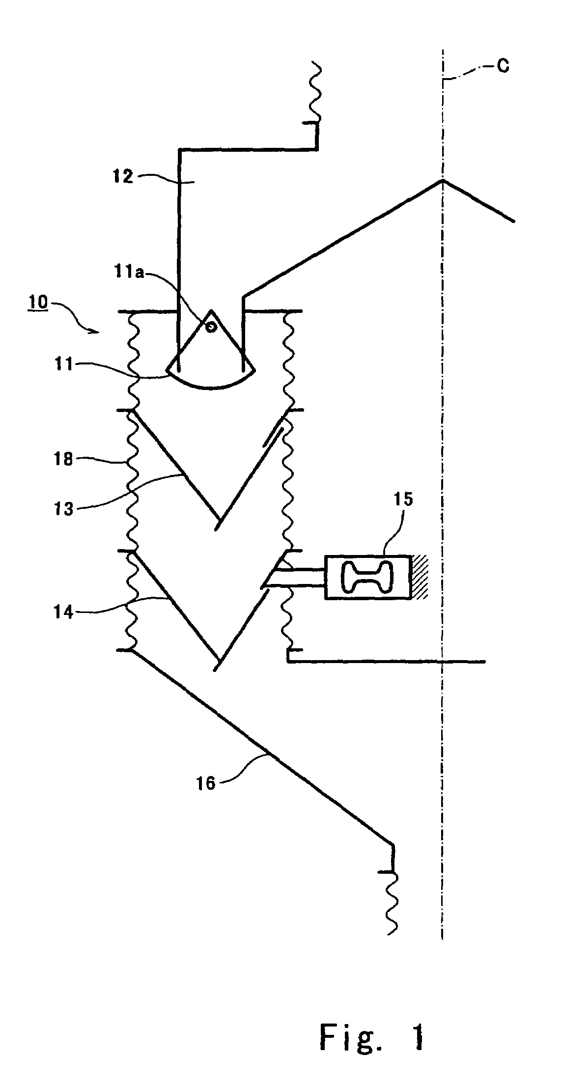
[0026]Hereinafter, preferred embodiments of the present invention are described with reference to the drawings. FIG. 1 is a schematic cross-sectional view showing a powdery- or granular-material weighing apparatus according to the present invention. Although the figure illustrates the cross-section of only one of scale units 10 that constitute the powdery- or granular-material weighing apparatus, the powdery- or granular-material weighing apparatus of the present embodiment has a configuration in which a plurality of the scale units 10 are provided around a center line C as the center. The same also applies to later-described embodiments shown in FIGS. 2 to 11.

[0027]The scale unit 10 in the present embodiment is provided with a cut gate 11 serving as a powdery- or granular-material supplying means, and the cut gate 11 is attached to a lower portion of a powdery or granular material hopper 12 for guiding a powdery or granular material supplied from above to each of the scale units 10...

second embodiment

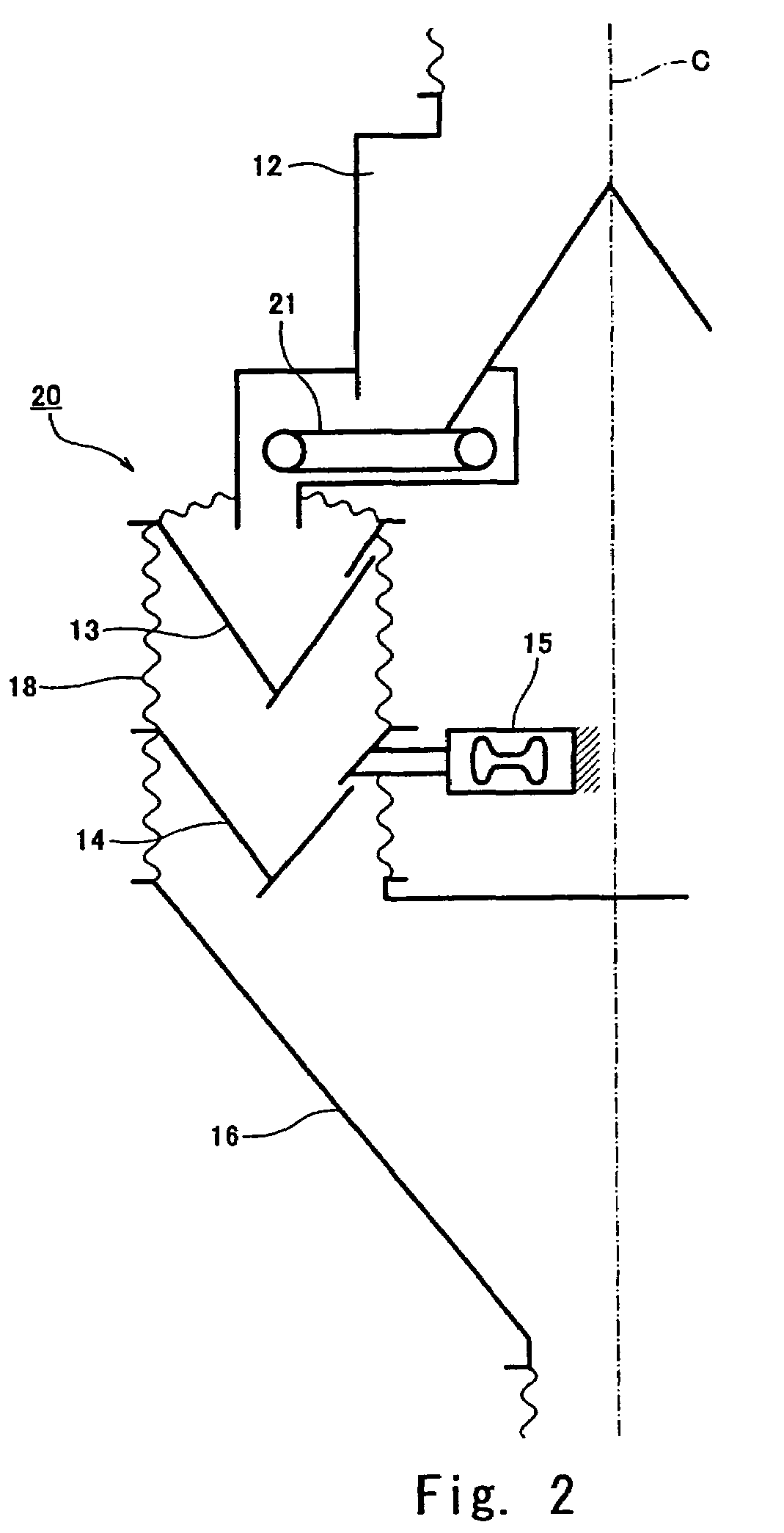
[0031]FIG. 2 is a schematic cross-sectional view of a powdery- or granular-material weighing apparatus according to the present invention. Scale units 20 in the powdery- or granular-material weighing apparatus of the present embodiment are identical to the above described scale unit 10 shown in FIG. 1, except that a belt feeder 21 is used as a powdery- or granular-material supplying means in place of the cut gate 11 in the scale unit 10, and identical corresponding parts are denoted by the same reference numerals.

[0032]In the powdery- or granular-material weighing apparatus of the present embodiment as well, a powdery or granular material is supplied from the belt feeder 21 to the feeding hopper 13 aiming at the individual target weight for each scale unit 20 as the target and, during that time, the powdery or granular material is supplied to the feeding hopper 13 approximately at a constant flow rate without performing the large quantity charging and the small quantity charging, or...

third embodiment

[0034]FIG. 3 is a schematic cross-sectional view of a powdery- or granular-material weighing apparatus according to the present invention. Scale units 30 in the powdery- or granular-material weighing apparatus of the present embodiment are identical to the above-described scale unit 10 shown in FIG. 1, except that a disk feeder 31 is used as a powdery- or granular-material supplying means in place of the cut gate 11 in the scale unit 10 and that the feeding hopper 13 is not provided, and identical corresponding parts are denoted by the same reference numerals. In the powdery- or granular-material weighing apparatus of the present embodiment, a powdery or granular material is supplied to the weighing hopper 14 by rotating a scraper 31a of the disk feeder 31 and opening a discharging gate 31b.

[0035]In the powdery- or granular-material weighing apparatus of the present embodiment, a powdery or granular material is supplied from the disk feeder 31 to the weighing hopper 14, aiming at t...


PUM

PropertyMeasurementUnit
Weightaaaaaaaaaa
Speedaaaaaaaaaa

Abstract

Each of a plurality of scale units 10 that constitute a combination weigher is provided with a cut gate 11 attached to a lower portion of a powdery- or granular-material hopper 12, a feeding hopper 13 for temporarily retaining a powdery or granular material supplied from the cut gate 11, a gate-type weighing hopper 14 for weighing the powdery or granular material supplied from the feeding hopper 13, and a collecting chute 16 for collecting the powdery or granular material discharged from each weighing hopper 14 and supplying it to a wrapping machine or the like. A load cell 15 is attached to the weighing hopper 14, and the load cell 15 measures the weight of the powdery or granular material for performing combinatorial computing between the weighing hoppers 14. A dust-preventing bellow 18 is provided in between the respective constituting components: the cut gate 11, the feeding hopper 13, the weighing hopper 14, and the collecting chute 16. This makes available a powdery- or granular-material weighing apparatus capable of weighing a powdery or granular material at high speed.

Description

TECHNICAL FIELD[0001]The present invention relates to a powdery- or granular-material weighing apparatus, and more particularly to a powdery- or granular-material weighing apparatus in which charging of a powdery or granular material to a weighing portion is performed by charging the material in parts into a plurality of scale units constituting a combination weigher so that the weighing speed is increased.BACKGROUND ART[0002]Conventionally, two-stage charging system weighing apparatuses have been used for weighing powder or granular materials to improve weighing speed and increase weighing accuracy. FIG. 12 represents the relationship of charging weight and charging flow rate with charging time in a two-stage charging system. As shown in FIG. 12, in the two-stage charging system weighing apparatus, a powdery or granular material is supplied to a weighing hopper at a large flow rate until the measurement of the weight of the powdery or granular material reaches about 90% of a target...

Claims


Application Information

Patent Timeline
IPC IPC(8): G01G19/387G01G13/18G01G19/393
CPCG01G19/393G01G17/06B29B7/60B29B7/24
Inventor KAWANISHI, SHOZOUSUI, KAZUONISHIKAWA, MITSUSHI
Owner YAMATO SCALE CO LTD
Learn More