
Liquid jet apparatus and printing apparatus

a liquid jet and printing apparatus technology, applied in printing, other printing apparatus, etc., can solve the problems of affecting the quality of printing, so as to achieve high quality, prevent the effect of emitted liquid jet weight variation, and suppress the effect of emitted liquid jet weigh

Inactive Publication Date: 2009-09-08
SEIKO EPSON CORP
View PDF11 Cites 18 Cited by
  • Summary
  • Abstract
  • Description
  • Claims
  • Application Information

AI Technical Summary

Benefits of technology

The present invention provides a liquid jet apparatus and a printing apparatus that can prevent waveform distortion of the drive pulse, suppress and prevent variation in the weight of the liquid, and prevent shift in liquid jet emission timing, resulting in high-quality and fine tone printing. The liquid jet apparatus includes a drive waveform signal generation unit, transistor pairs, low-pass filters, and modulator unit for pulse-modulation. The printing apparatus includes the liquid jet apparatus and a modulator unit for individual control of the actuators. The invention also provides a waveform data memory for generating drive waveform signals for each actuator and a drive waveform signal generation unit that generates drive waveform signals simultaneously to all the actuators. The invention reduces power loss and lowers power consumption, and allows for efficient arrangement of multiple liquid jet heads and downsizing of the printing apparatus.

Problems solved by technology

However, in the past inkjet printer, there is a problem that the waveform of the drive pulse is distorted by the parasitic inductance, the parasitic capacitance, and the resistance of the wiring of the drive circuit, and the capacitance of the actuator such as a piezoelectric element, and moreover, the amount of the waveform distortion varies in accordance with the number of the actuators such as the piezoelectric elements driven by the drive pulse.
The waveform distortion of the drive pulse leads to variation in the weight of the liquid, causing variation in the size of the liquid dot, thus leading to degradation of the print quality.
Further, in the case in which a plurality of drive pulses is combined in chronological order and joined to each other, the drive pulse corresponding to the tone grade of a liquid dot to be formed is selected for every nozzle from the plurality of drive pulses, and the selected drive pulse is applied to the actuator of the corresponding nozzle, there is caused a shift in the liquid jet emission timing between the nozzles of the actuators for which the different drive pulses are selected, thus the liquid dot forming (or landing) positions are varied to cause degradation of the print quality.

Method used


Image

  • Liquid jet apparatus and printing apparatus
  • Liquid jet apparatus and printing apparatus
  • Liquid jet apparatus and printing apparatus

Examples


Embodiment Construction

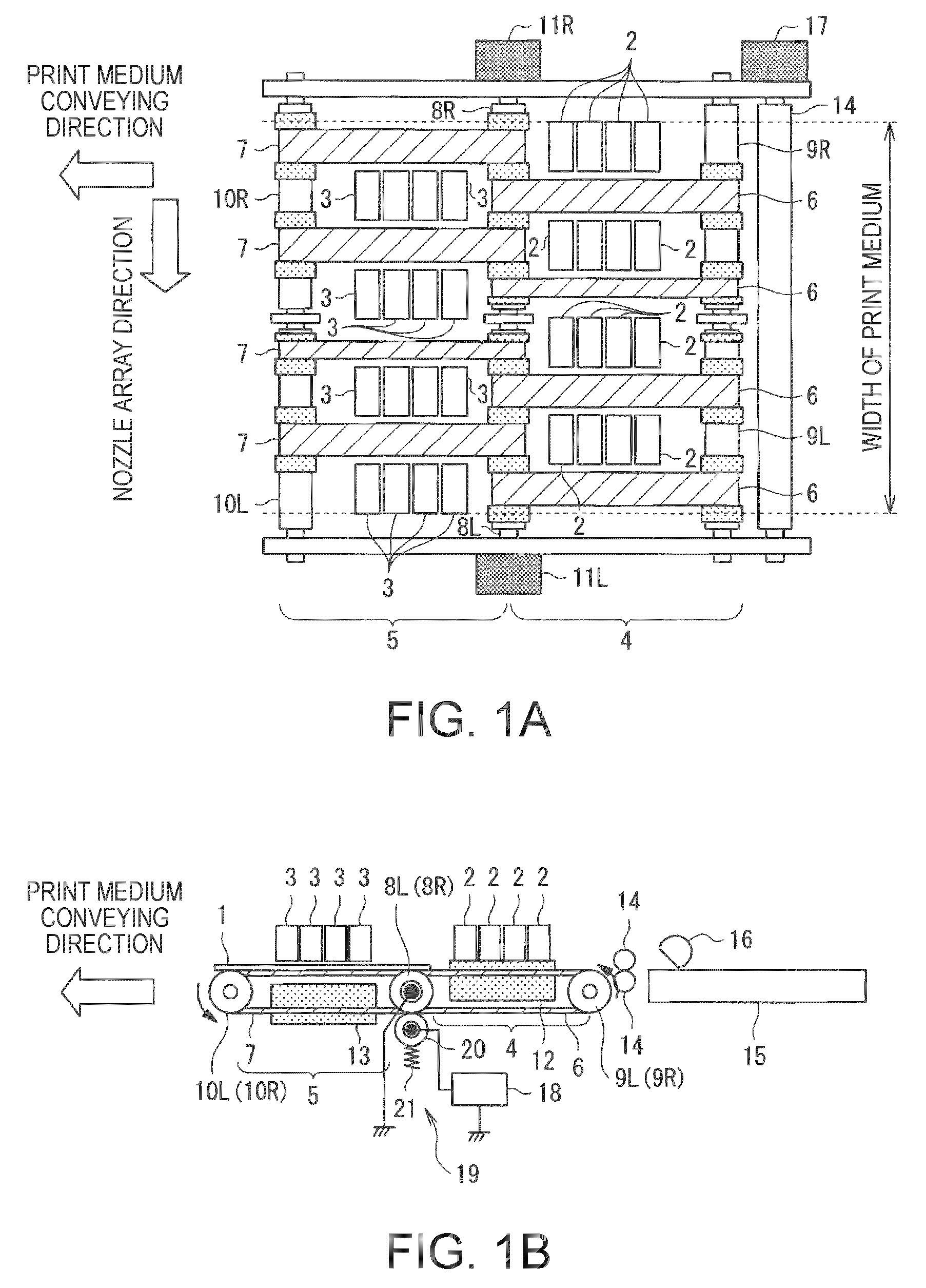
[0032]An embodiment will be explained with reference to the drawings using a printing apparatus for printing letters and images on a print medium by emitting a liquid jet, as an example of the present invention.

[0033]FIGS. 1A and 1B are schematic configuration views of the printing apparatus according to the present embodiment, wherein FIG. 1A is a plan view thereof, and FIG. 1B is a front view thereof. In FIG. 1, in the line head printing apparatus, a print medium 1 is conveyed from right to left of the drawing along the arrow direction, and is printed in a print area in the middle of the conveying path. It should be noted that the liquid jet head of the present embodiment is not disposed integrally in one place, but is disposed separately in two places.

[0034]The reference numeral 2 in the drawing denotes a first liquid jet head disposed on the upstream side in the conveying direction of the print medium 1, the reference numeral 3 denotes a second liquid jet head disposed similarly...


PUM


Abstract

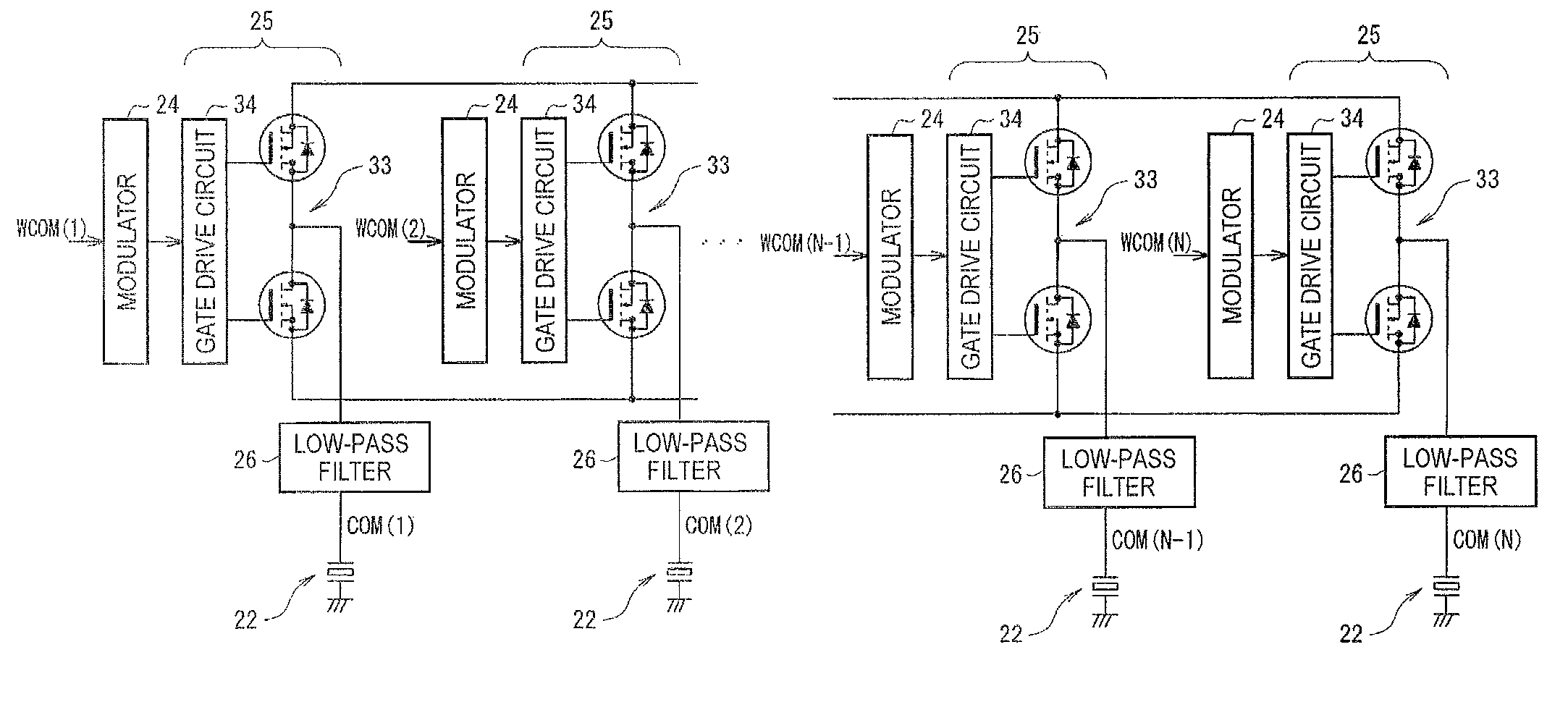
A liquid jet apparatus includes a plurality of nozzles provided to a liquid jet head, an actuator provided corresponding to each of the nozzles, and drive unit for applying a drive pulse to the actuator, wherein the drive unit includes drive waveform signal generation unit that generates one or more of drive waveform signals each providing basis of the drive pulse to the actuator, one or more of transistor pairs provided as many as the number of the actuators in order for power-amplifying the one or more of drive waveform signals generated by the drive waveform signal generation unit, and each having two transistors forming a pair and connected to each other in a push-pull manner, and one or more of low-pass filters provided as many as the number of the actuators and each disposed between a connection point of the transistor pair and the actuator.

Description

BACKGROUND[0001]1. Technical Field[0002]The present invention relates to a liquid jet apparatus and printing apparatus arranged to print predetermined letters and images by emitting microscopic droplets of liquids from a plurality of nozzles to form the microscopic particles (dots) thereof on a printing medium.[0003]2. Related Art[0004]An inkjet printer as one of such printing apparatuses, which is generally low-price and easily provides high quality color prints, has widely been spreading not only to offices but also to general users along with the widespread of personal computers or digital cameras.[0005]Further, in recent inkjet printers, printing in fine tone is required. Tone denotes a state of density of each color included in a pixel expressed by a liquid dot, the size of the dot corresponding to the color density of each pixel is called a tone grade, and the number of the tone grades capable of being expressed by a liquid dot is called a tone number. The fine tone denotes th...

Claims


Application Information

Patent Timeline
Patent Type & Authority Patents(United States)
IPC IPC(8): B41J29/38
CPCB41J2/04541B41J2/04578B41J2/04581B41J29/38B41J2/04593B41J2/04596B41J2/04588
Inventor TABATA, KUNIOOSHIMA, ATSUSHI
Owner SEIKO EPSON CORP
Learn More