Method for controlling measurement in injection molding machine, and injection molding machine

a technology of injection molding machine and measurement method, which is applied in the direction of auxillary shaping apparatus, manufacturing tools, food shaping, etc., can solve the problems of inability to increase the back pressure expected, unstable measurement operation, and inability to make molded items, so as to avoid drooling or cobwebbing, and the variation in weight between molded items can be made as low as possible

Inactive Publication Date: 2009-01-15
TOYO MACH & METAL CO LTD
View PDF4 Cites 2 Cited by
  • Summary
  • Abstract
  • Description
  • Claims
  • Application Information

AI Technical Summary

Benefits of technology

[0007]The present invention was developed in consideration of the foregoing problem. It is an object of the present invention to make all of a measured value of the astern speed of a screw, a measured value of the back pressure and a measured rotational velocity of the screw (measurement servo-motor) zero concurrently at timing when the screw reaches a position where measurement is completed, so that suck-back can be made dispensable.
[0013]According to the invention, control is made so that all the measured value of the astern speed of the screw, the measured value of the back pressure, and the measured rotational speed of the screw (measurement servo-motor) turn zero concurrently at timing when the screw reaches the measurement completion position. Accordingly, the residual pressure of molten resin staying in a heating cylinder till the next injection becomes zero. Thus, there is no fear that drooling or cobwebbing occurs when a mold is opened and a molded item is released from the mold. It is therefore unnecessary to perform suck-back after measurement is completed. In addition, since it is unnecessary to perform suck-back and any injection operation can be always started in a constant measurement completion position, the injection rate is stabilized, and the cushion thickness is also stabilized. Furthermore, the back pressure and the screw (measurement servo-motor) rotation turn zero as soon as the screw stops its astern movement. Thus, the variation in weight among molded items can be made as low as possible in cooperation with the stabilized density of the measured molten resin, the stabilized injection rate and the stabilized cushion thickness.

Problems solved by technology

Accordingly, in the beginning of measurement, shortage of raw resin leads to failure in expected increase of the back pressure.
As a result, the measuring operation may be unstable.
In addition, the measuring operation may be unstable in some operating condition of a raw resin supply system or in some dry condition of the resin.
In spite of such control, there is a problem that it cannot be guaranteed that all of a measured value of the astern speed of the screw controlled by the injection servo-motor, a measured value of the back pressure controlled by the measurement servo-motor and a measured rotational velocity of the screw turn zero concurrently at timing when the screw reaches a position where measurement is completed.
That is, in the background art, the deceleration setting pattern for the astern speed of the screw is not proper but is apt to be set to be steep.
Thus, the back pressure is adversely increased near the zero point of the astern speed of the screw.

Method used


Image

  • Method for controlling measurement in injection molding machine, and injection molding machine
  • Method for controlling measurement in injection molding machine, and injection molding machine
  • Method for controlling measurement in injection molding machine, and injection molding machine

Examples


Embodiment Construction

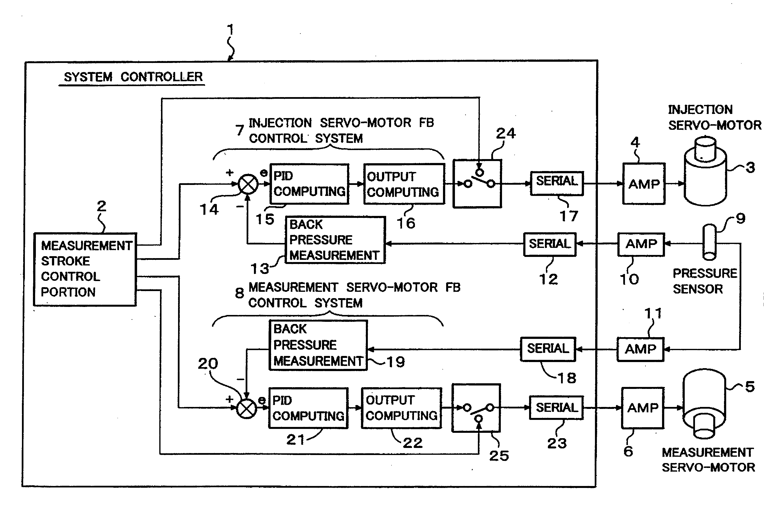
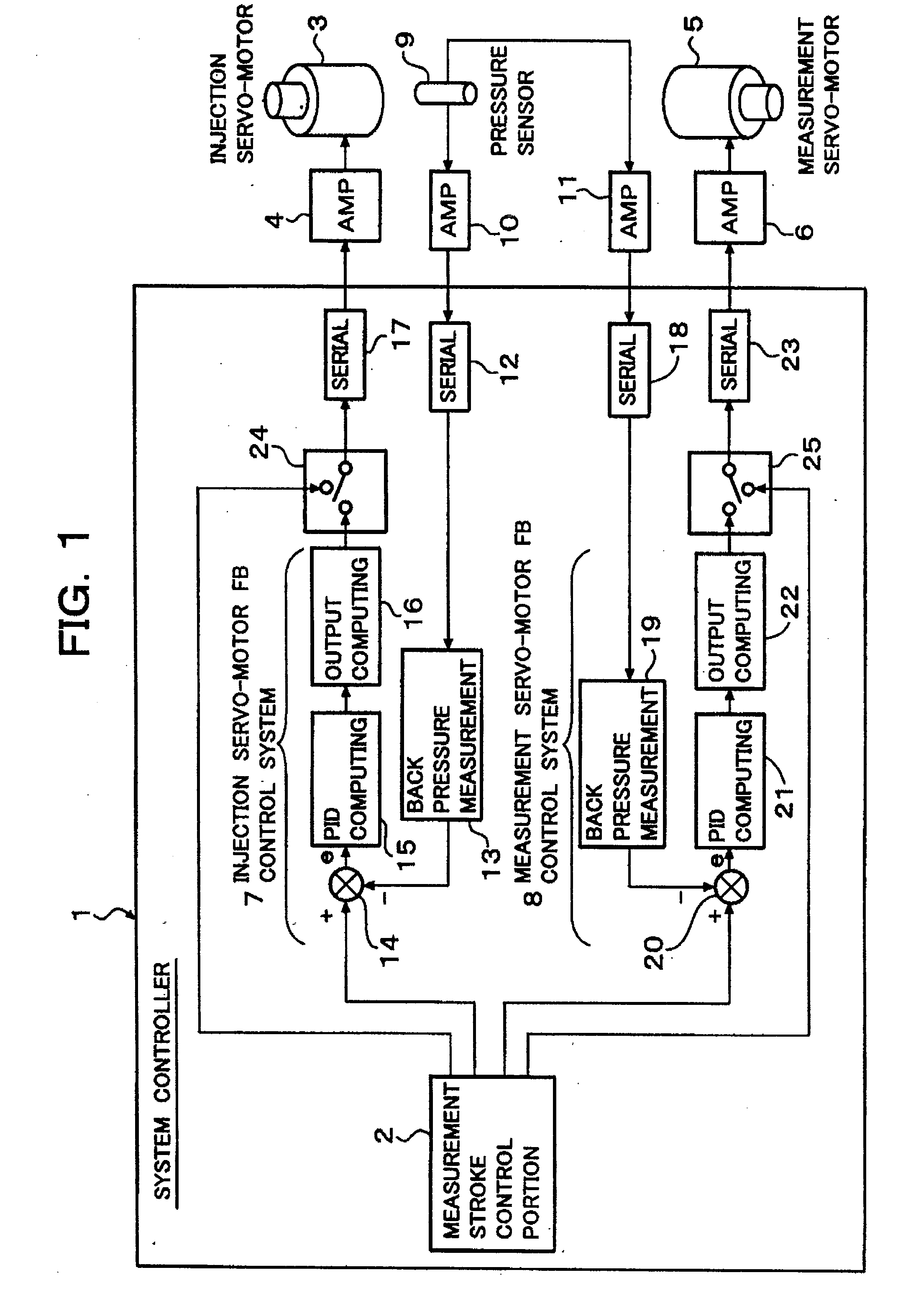
[0019]An embodiment of the present invention will be described below with reference to the drawings. FIG. 1 is a block diagram showing the configuration of a measurement control system in a motor-driven in-line screw type injection molding machine according to an embodiment of the present invention (hereinafter referred to as “this embodiment”).

[0020]In FIG. 1, the reference numeral 1 represents a system controller for administering control all over the injection molding machine. Here, only the configuration of a measurement control system is depicted in the system controller 1 in order to simplify the illustration.

[0021]In FIG. 1, the reference numeral 2 represents a measuring stroke control portion for administering host control of measurement operation. The measuring stroke control portion 2 supplies a command output directly to an amplifier 4 through a control changeover switch 24 and a serial port 17 so as to perform open control to control the driving of an injection servo-mot...


PUM

PropertyMeasurementUnit
distanceaaaaaaaaaa
timeaaaaaaaaaa
distance L3aaaaaaaaaa

Abstract

A method for controlling measurement in a motor-driven in-line screw type injection molding machine using servo-motors as a measurement driving source and an injection driving source. Control is made so that all of a measured value of back pressure controlled by the measurement servo-motor, a measured value of an astern speed of a screw controlled by the injection servo-motor, and a measured rotational speed of the screw turn zero concurrently at timing when the screw reaches a measurement completion position. Thus, suck-back can be made dispensable.

Description

FIELD OF THE INVENTION[0001]The present invention relates to a technique for controlling measurement in a motor-driven in-line screw type injection molding machine using servo-motors as a measurement driving source and an injection driving source.BACKGROUND ART[0002]In a motor-driven in-line screw type injection molding machine in the background art, a measuring stroke is often controlled as follows. That is, a measurement servo-motor is controlled by rotational velocity feedback control so that the rotational velocity of a screw coincides with a set value, while an injection servo-motor is controlled by pressure feedback control so that the back pressure applied onto the screw (resistant pressure against astern movement of the screw) coincides with a set value. When such rotational velocity feedback control is performed on the measurement servo-motor while such pressure feedback control is performed on the injection servo-motor, the back pressure applied to the screw is improved to...

Claims


Application Information

Patent Timeline
Patent Type & Authority Applications(United States)
IPC IPC(8): B29C45/76
CPCB29C45/76B29C2045/1792B29C2945/76665B29C2945/76568B29C2945/76605B29C2945/76498
Inventor YAMADA, AKIO
Owner TOYO MACH & METAL CO LTD
Why Eureka
Try Eureka